TECHNOLOGY EXPLAINER
Speed Reducers and Gears
— Types, accuracy, lifetime and materials of the part that slows rotation to gain force
In a robot joint, a speed reducer turns the motor’s fast rotation into slower rotation with more force. This article explains, in plain terms and with numerical examples, three types (planetary gears, strain wave gears or harmonic drives, and RV reducers): reduction ratio and torque, backlash and stiffness, the life formula, and materials and heat treatment.
For materials engineers, it shows where steel cleanliness and heat treatment, surface treatment, grease and 3D-printed plastic gears affect performance and life.
- Short version / before you read / place in the series
- Why reducers are needed
- Three types
- Reading the words of accuracy
- Lifetime and materials
- How to choose
- Limits and summary
- How to read the yardsticks and standards
- Glossary
- References
- Claim-to-source audit
Sourced = stated in a published source (link given)
Our calculation = a value this article calculated from stated assumptions
Not yet confirmed = drafts, plans, targets and other items that are not settled
Our own readings for materials and design are marked as commentary. Inference is shown in bold. Every analogy comes with its limits.
The maker values (rated torque, backlash, stiffness, lost motion, life) are maker-stated values for specific product series, and no third-party verification was found. Size, ratio and test conditions differ, so numbers from different products or types are not ranked. “Our calculation” applies catalog formulas and values or paper values with stated assumptions (such as efficiency 0.7); it is not the performance of a real machine. For standards only the number, title, edition and stage were checked, not the paid text. ASTM standards are not covered. Checked 25 October 2026.
1. The short version / what to know first / where this fits in the series
- A speed reducer turns the motor’s fast but weak rotation into slow but strong rotation. With a reduction ratio of 100 and an assumed efficiency of 0.7, a motor giving 0.5 N·m at 3000 rpm becomes a joint motion of 35 N·m at 30 rpmOur calculation.
- Three types play the lead: planetary gears, strain wave gears (harmonic drives) and RV (cycloidal) reducers. The basic patent for the strain wave gear was published in 1959Sourced[Ref. 1]. The makers state zero backlash for the gear elements of a strain wave gear, under 1 arc-min for the RV-E and under 3 arc-min for a planetary gearbox (HPG)Sourced[Ref. 2][Ref. 5][Ref. 4].
- Lifetime and accuracy depend on materials and use. The thin gear of a strain wave gear is often made of quenched and tempered medium-carbon low-alloy steel, and fatigue cracks start from non-metallic inclusions in the steel and from bending at the tooth rootSourced[Ref. 7]. Bearing life depends on the cube of torque, so using 1.2 times the rated torque cuts the expected life from 10,000 hours to about 5,800 hoursSourcedOur calculation[Ref. 2].
No prior knowledge is needed. A gear is a disc with teeth around its edge that transmits rotation by meshing. Two gears of different sizes meshed together change the speed and the force. Think of bicycle gears (where the analogy stops: on a bicycle the rider can change the pedalling speed, but a robot has a fixed ratio). The overall picture of robots is in the series article “Introduction to Drones and Robotics”.
The robot’s muscle (actuator) is a motor combined with a reducer. This article covers the reducer; the next one, on joint actuators, covers the whole joint including motor, sensors and control. Motor magnets are in the article on permanent magnets and rare earths, and lightweight structural materials in the one on structural materials for robots and drones.
2. Why reducers are needed: motors are fast but weak
An electric motor is efficient when it spins fast, but the force (torque) it gives per turn is small. A robot joint, however, must move slowly and with large force: think of lifting a load held at the end of an arm. That is why a reducer is placed in between.
Power (the rate of doing work) is torque multiplied by rotational speed. A reducer does not create power: it divides the speed by N and multiplies the torque by about N. Friction wastes some, so the output torque is input x N x efficiency.
What is sacrificed when the ratio goes up
It is tempting to think that a higher ratio is simply better because it gives more force. There is a price. The effect of the motor rotor’s weight on the output side grows with the square of the ratio N. This is called reflected inertia. The MIT Cheetah paper approximates it as proportional to the square of the gear ratioSourced[Ref. 8].
When you push a joint from the output side, a high ratio means turning the motor rotor N times faster, which feels very heavy. That is reflected inertia. It is less “heavy” than “will not budge”, and an impact from hitting the floor goes straight into the gears. The ability to be moved by an outside push is called backdrivability, and it is higher when the ratio is lower.
The facts: The MIT Cheetah paper states that a low gear ratio reduces reflected inertia but costs more Joule heating (motor heat) to produce torque. Conversely, a ratio that is too high may break a leg on contact or prevent a desired dynamic motionSourced[Ref. 8]. The robot in that paper used a single-stage planetary gear of 1:5.8 in its legSourced[Ref. 8]. The ratio is a balance to be sought for each use.
3. Three types: planetary, strain wave and RV
The reducers used in robot joints fall mainly into three types. For each, we look at the mechanism, then the ratio formula, then the values the makers state.
(1) Planetary gears
A central sun gear is circled by several planet gears, all surrounded by a ring gear. If the sun is the input, the ring is fixed and the arm carrying the planets (the carrier) is the output, the ratio is 1 + ring teeth / sun teeth. With 20 sun teeth and 60 ring teeth the ratio is 1 + 60 / 20 = 4Our calculation. Several planets share the load, which makes the unit small and strong (commentary).
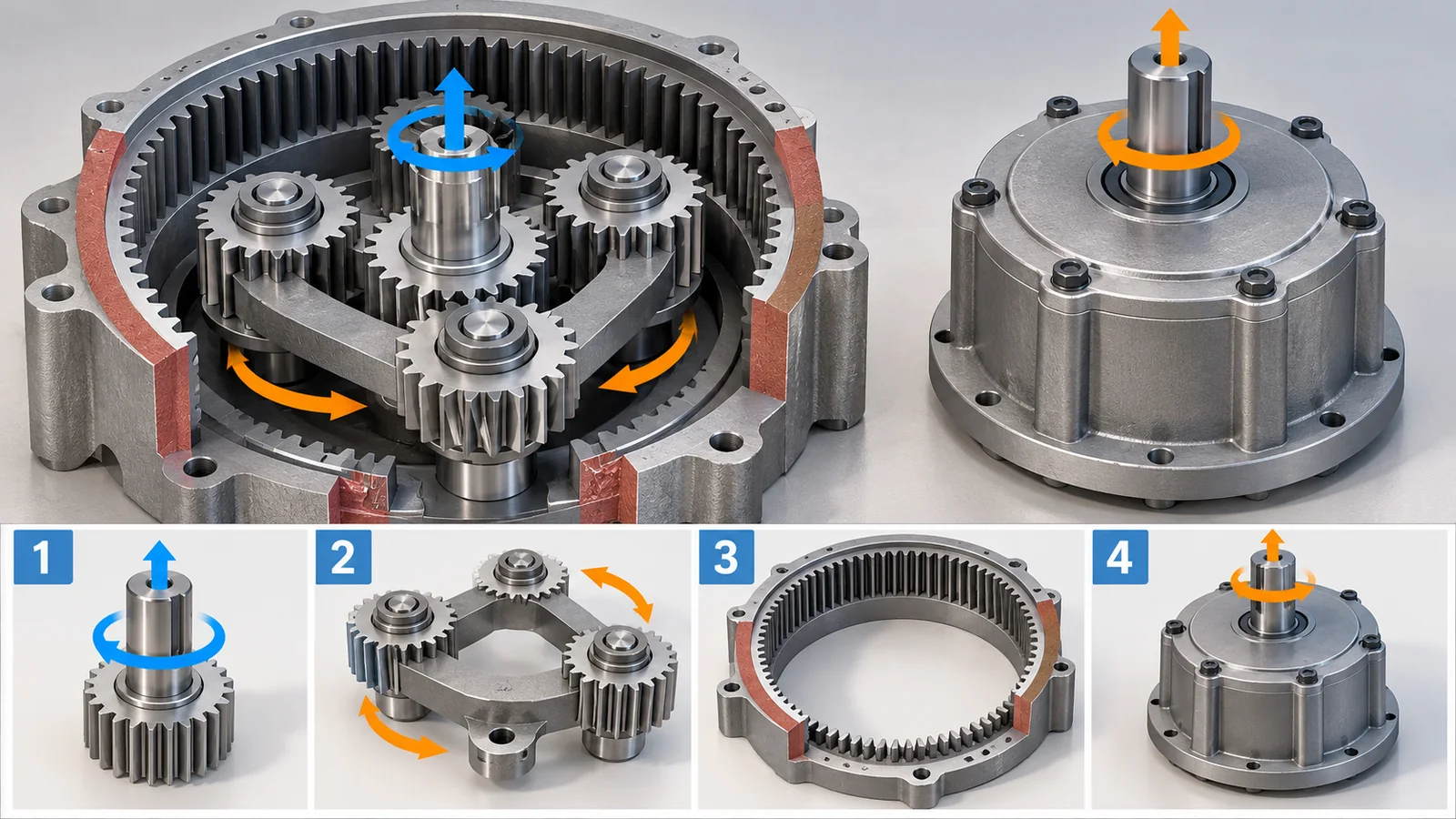
Original SVG, detailed explanation and sources
Original SVG reference: Concept diagram (vector drawing). Concept diagram of a planetary gear. The tooth counts are an example, not a specific product. The HPG ratios and backlash are maker-stated values from the Harmonic Drive LLC product page.
Harmonic Drive LLC states for its HPG planetary gearbox ratios of 3:1 to 50:1, backlash under 3 arc-min (under 1 arc-min as an option) and repeatability of +/-20 arc-secSourced[Ref. 4]. The MIT Cheetah leg used a single-stage planetary gear with four planets; the paper explains that 1:5.8 was the largest single-stage ratio available for a standard planetary configurationSourced[Ref. 8].
(2) Strain wave gears (harmonic drives)
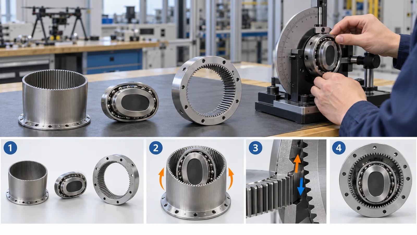
A strain wave gear has three parts: (1) a thin, flexible cup-shaped gear (the flexspline); (2) a rigid circular spline around it with two more teeth; and (3) an elliptical cam with a thin bearing inside (the wave generator). The cam flexes the flexspline into an ellipse, so the teeth mesh only at two places on the long axis. One turn of the cam makes the flexspline lag by two teethSourced[Ref. 2].
If the circular spline is fixed, the cam is the input and the flexspline the output, the ratio is flexspline teeth divided by the tooth difference (2). For a 200-tooth flexspline that is 200 / 2 = 100Our calculation. A single pair achieves a ratio that would take several planetary stages.
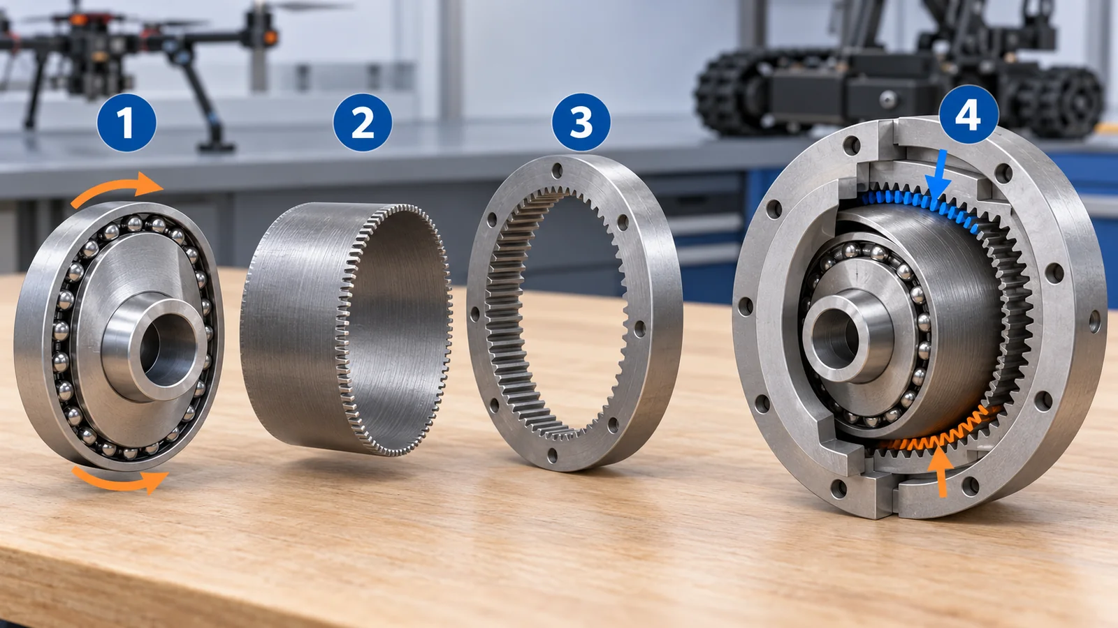
Original SVG, detailed explanation and sources
Original SVG reference: Concept diagram (vector drawing). Concept diagram of a strain wave gear. The ellipse and tooth shapes are exaggerated and the tooth counts are an example. The part names and operation follow the Harmonic Drive LLC catalog.
The type was devised by Musser and set out in US Patent 2,906,143 (filed 1955, published 1959)Sourced[Ref. 1]. According to the Harmonic Drive catalog, its current “S” tooth profile raises the share of teeth in mesh at the same time from about 15% to up to 30%, and about doubles the torsional stiffness at low to mid torqueSourced[Ref. 2]. The gear element is stated to have zero backlash, but the same catalog says the Oldham coupling that links it to the motor adds a small amount of backlashSourced[Ref. 2].
(3) RV (cycloidal) reducers
An RV reducer reduces in two stages. The first is a spur gear; the second is a combination of an “RV gear” that moves with a rocking motion on an eccentric shaft, and a ring of “pins” around it. There is one more pin than RV gear teeth, so each turn of the eccentric shaft advances the RV gear by one pin. The maker explains that many teeth touch the pins at once, giving a compact unit that withstands overloadSourced[Ref. 6].
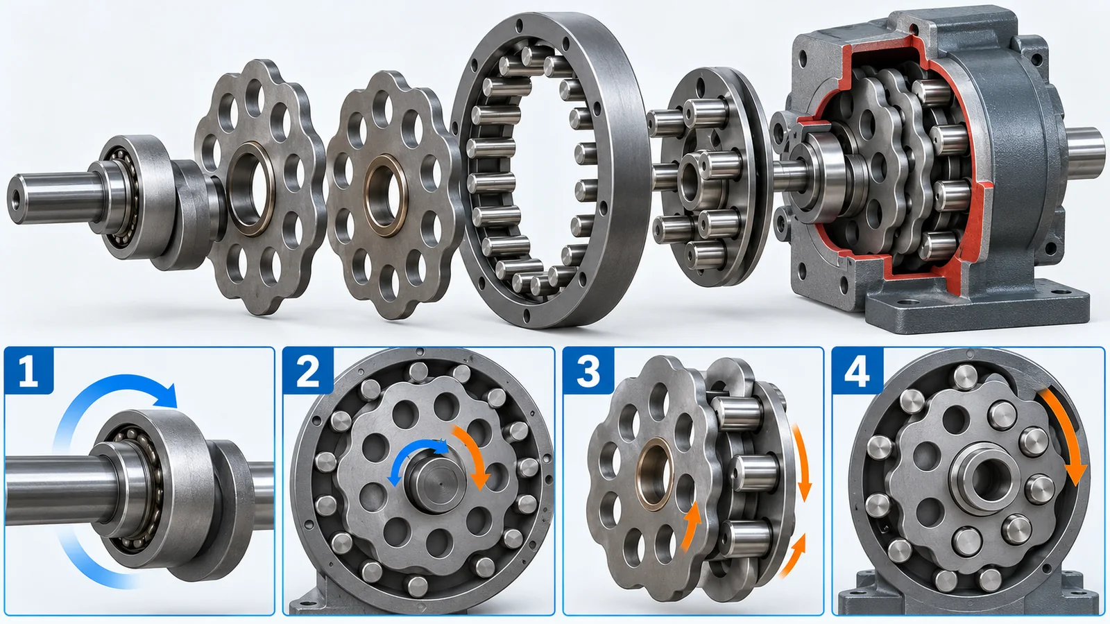
Original SVG, detailed explanation and sources
Original SVG reference: Concept diagram (vector drawing). Concept diagram of an RV reducer. The eccentricity and pin count are exaggerated. The backlash and lost motion values are maker-stated values on the Nabtesco RV-E series page.
The Nabtesco RV-E series page states backlash and lost motion (the angular play when the load is reversed) of under 1 arc-min each, with a built-in main bearingSourced[Ref. 5].
| Type | Mechanism in brief | Ratio examples (maker material) | Angular play (maker-stated) | Characteristics (commentary) |
|---|---|---|---|---|
| Planetary | Sun, planets and ring; several planets share the load | HPG: 3:1 to 50:1[Ref. 4] | Backlash under 3 arc-min (under 1 arc-min optional) | Modest ratio per stage and easy to backdrive; robust and suited to volume production |
| Strain wave | A cam flexes a thin gear; reduction comes from a two-tooth difference | Examples in the CSG catalog table: 50 to 160[Ref. 2] | Gear element zero (stated); typical hysteresis loss 1 to 3 arc-min (by ratio and size)[Ref. 2] | Large ratio in one stage; fatigue of the thin gear sets the life; short axially |
| RV (cycloidal) | An eccentric rocking gear and pins; two stages | Ratios vary by model (values not confirmed here) | Backlash and lost motion both under 1 arc-min (RV-E)[Ref. 5] | Described as stiff and shock-resistant; somewhat heavy, with built-in bearings |
Maker-stated values belong to specific product series, not to the type as a whole. Size, ratio and test conditions differ, so this is not a table for ranking the three types. The characteristics column is our commentary.
4. Reading the words of accuracy: backlash, lost motion and stiffness
Reducer catalogs list several words about angle. Each describes, from a different side, how far the output shaft can be from the angle you intended.
| Term | Plain meaning (commentary) | How catalogs treat it (examples) |
|---|---|---|
| Backlash | The gap between teeth: the angle the output can be pushed with the input held | Zero for the gear element of a strain wave gear (stated); under 1 arc-min for RV-E; under 3 arc-min for HPG[Ref. 2][Ref. 5][Ref. 4] |
| Lost motion | How much angle is not recovered when the load is reversed; includes elastic deflection as well as gaps | Under 1 arc-min for RV-E (maker-stated)[Ref. 5] |
| Hysteresis loss | The width of the twist-angle loop when torque is raised and lowered between zero and rated | Measured with the input locked, from 0 to +/- rated torque; typical 1 to 3 arc-min by ratio and size[Ref. 2] |
| Torsional stiffness | How stiff the output is against twisting under torque (N·m/rad): the slope of the curve | The curve is approximated by three straight lines (K1, K2, K3)[Ref. 2] |
| Angular accuracy | The difference from the output angle expected from the input angle | Standard accuracy of CSG-14-100: 1.5 arc-min (maker-stated)[Ref. 3] |
Definitions and test methods may differ between makers, and we did not check the details (test conditions) of each definition. The plain meanings are our commentary.
An arc-minute is one sixtieth of a degree. In radians that is about 0.00029 rad. A 1 arc-min error at the tip of a 0.5 m arm is 0.5 m x 0.00029 = about 0.15 mmOur calculation; at 1 m it is about 0.29 mm. An “arc-second” is a further sixtieth.
Sometimes stiffness matters more than backlash
Let us use the stiffness values (maker-stated) of the strain wave gear CSG-14-100 to calculate how much it actually twists. The rated torque is 10 N·m and the stiffness has three steps: K1 = 0.47×10⁴ N·m/rad (0 to 2 N·m), K2 = 0.61×10⁴ (2 to 6.9 N·m) and K3 = 0.71×10⁴ (above that)Sourced[Ref. 3]. Following the catalog’s method, we add up the twist at torque T.
The result at 10 N·m is 2/4700 + 4.9/6100 + 3.1/7100 = about 0.00167 rad, or about 5.7 arc-min of twistOur calculation. For a 0.5 m arm that corresponds to about 0.83 mm of deflection at the tip. The twist under load is larger than the catalog’s angular accuracy (1.5 arc-min). They are different quantities, but the key point for materials and design is that under load, stiffness governs the error at the tip (commentary).
Torsional stiffness depends on the shape of the gear (thickness, number of teeth in contact) and on the elasticity (Young’s modulus) of the material. Steel has a far higher modulus than plastics, so the same shape is stiffer in steel. A study of 3D-printed plastic gears (Berkeley Humanoid Lite) measured a torsional stiffness of about 319 N·m/rad for a PLA cycloidal gearbox, and says a similar study with carbon-fiber-reinforced polyamide reported about 1,468 N·m/radSourced[Ref. 9]. This shows the effect of material on stiffness, but size and conditions differ, so the numbers are not for ranking.
5. Lifetime and materials: what fails first
A strain wave gear has two main parts that decide its life: (1) the wave generator bearing (rolling fatigue) and (2) the flexspline (fatigue from repeated bending). The Harmonic Drive catalog says the normal life is set by the bearingSourced[Ref. 2].
(1) Bearing life falls with the cube of torque
The catalog’s expected-life formula is Lh = L10 x (Tr / Tav)^3 x (Nr / Nav). L10 is the time until 10 percent of units fail at rated torque Tr and 2000 rpm input (7,000 hours for CSF, 10,000 hours for CSG); Tav is the average load torque and Nav the average input speedSourced[Ref. 2].
Checking with numbers (Our calculation): at 1.2 times rated torque and 2000 rpm, 10,000 x (1/1.2)^3 = about 5,787 hours, or about 58% of the rated life. At 1.5 times it is about 2,963 hours (30%). At 0.8 times it is about 19,531 hours, nearly double. A design that lowers the torque a little pays off greatly in life.
The international standard ISO 281 also defines dynamic load ratings and rating life for rolling bearings (2007 edition, at the stage “to be revised”)Sourced[Ref. 15]. That bearing life falls as a power of the load is common to bearings in general (commentary).
(2) The flexspline is a fight against fatigue
The flexspline is a thin gear bent into an ellipse each time the cam turns. The catalog explains that the rated torque and the allowable repeated peak torque assume an infinite fatigue life of the flexspline, and that momentary peak torques such as those in a collision are limited in number. When excessive torque stops the teeth meshing properly, the phenomenon is called ratcheting and leads to tooth wear and fatigue failureSourced[Ref. 2].
A 2026 review (Lian et al.) lists, as one of the materials widely used for commercial flexsplines, medium-carbon low-alloy steels (40CrNiMoA, 35CrMnSiA). Quenching and tempering give high strength and toughness at moderate cost, so they are the most widely used for industrial-robot flexsplines, and fatigue cracks start from non-metallic inclusions and from bending at the tooth root. It also mentions high-strength maraging steelSourced[Ref. 7].
Quenching hardens steel by cooling it rapidly from a high temperature. Hard steel alone cracks easily, so tempering raises the temperature a little to restore toughness. Together the two are called quenching and tempering. Non-metallic inclusions are small particles of oxides or sulfides left in the steel during steelmaking; under repeated loading they become starting points of cracks (commentary). The review above describes cases where alumina (Al₂O₃) particles and elongated MnS (manganese sulfide) stringers were crack-initiation sitesSourced[Ref. 7].
Fatigue starts from the single weakest point. So in a thin gear, the size and number of inclusions (steel cleanliness) matter more than the average strength. Surface treatment matters too. The same review summarizes a report that shot peening (hitting the surface with small steel balls to create compressive residual stress) extended fatigue life by up to 66%, and says nitriding helps both wear and fatigue but its processing temperature of 500 to 600 C may cause thermal deformation in a thin gearSourced[Ref. 7]. These are summaries of the literature, not values we verified ourselves.
(3) The lubricant (grease) is also a part
Reducer efficiency and life also depend on the lubricant. The catalog explains that efficiency depends on ratio, input speed, load torque, temperature and the amount and type of lubricant, and that a compensation coefficient is used when the load is below the rated torque. Dedicated greases (such as SK-1A) are provided. At the low end of the temperature range the viscosity rises and efficiency falls; at the high end the lubricant degrades faster and life shortensSourced[Ref. 2]. If the wave generator is fully submerged in oil, churning raises heat and lowers efficiency, so an oil level covering about half of the bearing is recommendedSourced[Ref. 2].
6. How to choose: three design philosophies
The choice of reducer depends on what the robot is for. Here are three philosophies, each with an example from a primary source.
- Prioritize accuracy and stiffness (industrial robot arms and the like): a strain wave or RV reducer with a large ratio holds position accurately. Backlash can be small and holding force is large, but reflected inertia is high and backdrivability is low.
- Prioritize impact tolerance and force control (legged robots and the like): the MIT Cheetah leg used a low ratio (1:5.8) planetary gear and a high-torque motor to soften the impact of landing and to control joint force. The paper calls this “proprioceptive actuation” and expresses impact mitigation through backdrivability with a new metric, the impact mitigation factor (IMF)Sourced[Ref. 8].
- Prioritize availability and cost (research and education): Berkeley Humanoid Lite uses PLA plastic cycloidal gears printed on a 3D printer in its actuators and kept the parts cost of the whole robot under US$5,000. Mechanical efficiency was about 90% in most conditions; in a 60-hour durability test efficiency stayed stable and backlash rose slowly with wear, but the authors call it within acceptable limitsSourced[Ref. 9].
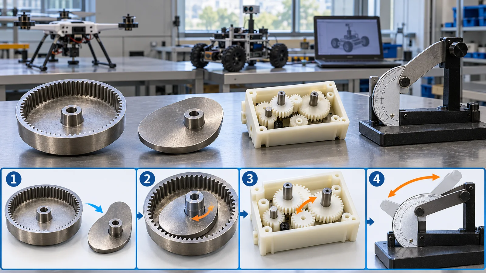
The MIT Cheetah shoulder module had motors of 2.00 kg, a heat-treated steel gear train of 0.42 kg and framing of 1.23 kg, for a total of 3.65 kgSourced[Ref. 8]. The gears are about 12% of the weight (0.42 / 3.65); in this example the motors weigh far moreOur calculation. Plastic gears, on the other hand, may win on weight and price but are limited in stiffness and wear resistance (numbers above). The gear material is chosen by balancing strength, weight, lifetime, cost and availability (commentary).
7. Limits, what could not be confirmed, and a summary
- The makers’ values are stated values for specific products. The values for CSG-14-100, RV-E and HPG come from each product page or catalog, and no independent third-party verification was found. Size, ratio and test conditions differ, so no ranking among types is made.
- The ratio formula and values such as rated torque for the RV reducer were not confirmed. The specification table on the product page is split into separate columns and rows, and individual values could not be read in this survey.
- No efficiency values are given for the strain wave gear. The catalog shows efficiency as graphs and we did not read numbers from them.
- No international standard for the performance of a reducer alone was found. ISO 9283 covers the pose performance of robots, ISO 6336 and related parts cover gear strength calculation, and ISO 281 covers bearing life. How angular accuracy, stiffness and hysteresis are measured follows each maker’s definition.
- Detailed material standards (JIS and ISO steel grades) and fatigue test values are not covered. Steel types are limited to what a 2026 review describes. Effects such as the up-to-66% gain from shot peening are literature values collected in the review and were not verified by us.
- The durability of 3D-printed gears comes from a single study. The 60-hour test of the PLA cycloidal gearbox was the authors’ test on one model under limited conditions and cannot be generalized.
- A reducer divides the speed by N and multiplies torque by about N. Reflected inertia, however, grows with N squared and backdrivability falls. A higher ratio is not always betterOur calculation[Ref. 8]
- Each of the three types has its own strengths. Planetary gears are robust with modest ratios, strain wave gears give a large ratio in one stage, and RV reducers are described as stiff and shock-resistant. The values are maker-stated and the table is not for rankingSourced
- Stiffness governs the error at the tip. CSG-14-100 twists about 5.7 arc-min at rated torque, equal to about 0.83 mm at the tip of a 0.5 m arm (calculated from catalog values)Our calculation
- Life is governed by the cube of torque. About 58% at 1.2 times rated torque and about double at 0.8 times. The life of a thin gear depends on steel inclusions, tooth-root bending and surface treatmentOur calculationSourced[Ref. 7]
- Gear materials are chosen by balancing strength, weight, lifetime, cost and availability. 3D-printed plastic gears are cheap to try but limited in stiffness and wearSourced[Ref. 9]
8. How to read the yardsticks and standards
The “quality” of a reducer cannot be expressed by one number. It results from a combination of reduction ratio, rated torque, backlash and lost motion, torsional stiffness, efficiency, life and weight. What matters is that the same word gives different numbers under different test conditions. Efficiency, for example, changes with load torque, temperature and lubricant, and life means something different depending on whether it is the time until 10% (L10) or 50% (L50) of units fail[Ref. 2]. The table below organizes what could be confirmed (checked on 25 October 2026).
| What is evaluated | Typical tests and benchmarks (name, source) | Standards, rules and guidance (ISO, IEC, JIS and others) | Reading notes |
|---|---|---|---|
| Pose performance of a robot | How to measure pose accuracy and repeatability (ISO 9283) | ISO 9283:1998 “Manipulating industrial robots — Performance criteria and related test methods” (confirmed in 2021, now under review)[Ref. 10]Sourced | This is for the whole robot, not for the reducer alone. The test details were not checked (paid text) |
| Accuracy, stiffness, hysteresis and efficiency of the reducer alone | Maker-defined tests: lock the input and measure twist from 0 to +/- rated torque (hysteresis); stiffness approximated by three lines[Ref. 2]Sourced | Not found (no international standard for the reducer alone was confirmed) | Definitions and conditions may differ between makers. Do not compare values of the same name directly |
| Gear strength design | — (calculation standards) | ISO 6336-1:2019 (basic principles) and ISO 6336-5:2016 (strength and quality of materials); both at the confirmed stage[Ref. 11, 12]Sourced | Standards for the load capacity of spur and helical gears. Whether they apply directly to the thin gear of a strain wave gear was not confirmed |
| Tooth accuracy | — (accuracy-grade standard) | ISO 1328-1:2013 (definitions and allowable values of flank deviations; confirmed)[Ref. 13]Sourced | A standard for cylindrical gears; the values themselves were not checked |
| Terms | — (vocabulary) | ISO 1122-1:1998 (gear terms, geometry; stage 90.60 “under review”)[Ref. 14]SourcedNot yet confirmed | The basis for definitions such as backlash. It is under review and a future edition may change |
| Bearing life | The maker’s expected-life formula (L10, L50)[Ref. 2]Sourced | ISO 281:2007 (dynamic load ratings and rating life; stage 90.92 “to be revised”)[Ref. 15]SourcedNot yet confirmed | L10 is the time until 10 percent fail; it is not an average |
| Metrics for comparing actuators | Impact mitigation factor (IMF) for backdrivability (Wensing et al., 2017); efficiency, stiffness and durability tests (Berkeley Humanoid Lite)[Ref. 8][Ref. 9]Sourced | Not found | These are metrics from research papers, not standards, and are based on the design of single robots |
| Material fatigue and surface treatment | Results of fatigue tests and analyses collected in a review (Lian et al., 2026)[Ref. 7]Sourced | ISO 6336-5 (strength and quality of materials)[Ref. 12] | Numbers in the review are quoted from the literature, and conditions (steel, shape, load) differ between studies |
The table layout is our organization (Our calculation). Numbers, titles and stages were checked on ISO’s official pages (checked 25 October 2026). Standard texts are paid, so only titles and scope are given. ASTM standards are not covered.
Reading notes (for materials engineers)
- A catalog “rated torque” comes together with life and speed. The Harmonic Drive rated torque is a continuous load at 2000 rpm input and is given together with the rated life L10[Ref. 2]. At other speeds or duty, the same product has a different life.
- A maker’s stated value and third-party verification are different. Backlash and accuracy values are from the maker’s test conditions and are not necessarily what a third party would measure under the same conditions.
- Standards may be recommendations or requirements. It is generally understood that an ISO standard binds mainly when cited by law or contract (commentary).
- Laboratory values and the field differ. Grease temperature, mounting accuracy and shock loads change life and efficiency. The catalog itself draws attention to lubricant quantity and temperature range[Ref. 2].
9. Glossary
- Speed reducer
- A part that slows the motor’s rotation and increases torque.
- Reduction ratio
- Input speed divided by output speed. At 100, the output turns at one hundredth of the speed.
- Torque
- The force that turns something; unit N·m.
- Power
- Torque times angular speed: the rate of doing work. Unit W.
- Efficiency
- Output power divided by input power; below 1 because of friction and other losses.
- Backlash
- The gap between teeth: the angle the output moves when pushed with the input held.
- Lost motion
- The angle not recovered when the load is reversed.
- Hysteresis
- The mismatch in twist angle between loading and unloading.
- Torsional stiffness
- Resistance to twisting; unit N·m/rad. Larger means stiffer.
- Arc-minute (arc-min)
- One sixtieth of a degree; about 0.00029 rad.
- Reflected inertia
- The effect that the motor rotor looks like N squared times the inertia when seen from the output.
- Backdrivability
- The ability to be moved from the output side, motor included.
- Planetary gear
- A reducer combining sun, planet and ring gears.
- Strain wave gear
- The harmonic drive: a reducer in which a cam flexes a thin gear.
- Flexspline
- The thin, flexible cup-shaped gear of a strain wave gear.
- Circular spline
- The rigid ring with internal teeth in a strain wave gear.
- Wave generator
- The elliptical cam and thin bearing of a strain wave gear.
- RV reducer
- A two-stage reducer using an eccentrically rocking gear and pins.
- L10 life
- The time until 10 percent of units fail.
- Ratcheting
- The failure of strain wave gear teeth to mesh properly under excessive torque.
- Quenching and tempering
- Hardening followed by tempering: a heat treatment that balances strength and toughness.
- Non-metallic inclusion
- Oxide or sulfide particles left in steel; starting points of fatigue cracks.
- Shot peening
- Hitting the surface with small steel balls to create compressive residual stress.
- Impact mitigation factor (IMF)
- A metric for how well backdrivability mitigates impact.
- Torque density
- Torque per unit mass (or volume).
10. References (primary sources)
- Musser C. W. US Patent 2,906,143 “Strain wave gearing” (filed 21 March 1955, published 29 September 1959; assignee United Shoe Machinery Corp) — patents.google.com/patent/US2906143A/en
- Harmonic Drive LLC “CSF/CSG Component Sets and Housed Units” catalog (principle, rating definitions, life equation, stiffness, hysteresis, efficiency notes) — harmonicdrive.net/_hd/content/documents/csf-csg.pdf
- Harmonic Drive LLC Product page CSG-14-100-2A-R-BB-LW (maker-stated rated torque, stiffness, mass and other values) — harmonicdrive.net/products/component-sets/cup-type/csg-2a-lw/csg-14-100-2a-r-bb-lw
- Harmonic Drive LLC Product page HPG Planetary Gearbox (maker-stated ratios 3:1 to 50:1, backlash under 3 arc-min and other values) — harmonicdrive.net/products/servo-mount-gearheads/harmonic-planetary/hpg-planetary-gearbox
- Nabtesco “RV-E” product page (maker-stated backlash and lost motion under 1 arc-min) — precision.nabtesco.com/en/products/detail/RV-E
- Nabtesco “Introduction” (explanation of the operating principle of the RV reducer) — precision.nabtesco.com/en/products/introduction/
- Lian X., Liu J., Li Y., Li W. “Research Progress on Mechanical Properties and Fatigue Failure of Harmonic Drive Flexspline”, Sensors 26(13), 4204 (2026), DOI 10.3390/s26134204 — mdpi.com/1424-8220/26/13/4204
- Wensing P. M., Wang A., Seok S., Otten D., Lang J., Kim S. “Proprioceptive Actuator Design in the MIT Cheetah: Impact Mitigation and High-Bandwidth Physical Interaction for Dynamic Legged Robots”, IEEE Transactions on Robotics 33(3), 509–522 (2017), DOI 10.1109/TRO.2016.2640183 — dspace.mit.edu/entities/publication/8b15bcc8-c288-43aa-b923-69ce3c13b818
- Chi Y. et al. “Demonstrating Berkeley Humanoid Lite: An Open-source, Accessible, and Customizable 3D-printed Humanoid Robot”, arXiv:2504.17249 (2025) — arxiv.org/abs/2504.17249
- ISO ISO 9283:1998 “Manipulating industrial robots — Performance criteria and related test methods” (April 1998; confirmed in 2021; stage 90.60 “under review”) — iso.org/standard/22244.html
- ISO ISO 6336-1:2019 “Calculation of load capacity of spur and helical gears — Part 1: Basic principles, introduction and general influence factors” (November 2019, confirmed) — iso.org/standard/63819.html
- ISO ISO 6336-5:2016 “Calculation of load capacity of spur and helical gears — Part 5: Strength and quality of materials” (August 2016, confirmed) — iso.org/standard/55353.html
- ISO ISO 1328-1:2013 “Cylindrical gears — ISO system of flank tolerance classification — Part 1: Definitions and allowable values of deviations relevant to flanks of gear teeth” (September 2013, confirmed) — iso.org/standard/45309.html
- ISO ISO 1122-1:1998 “Vocabulary of gear terms — Part 1: Definitions related to geometry” (August 1998; stage 90.60 “under review”) — iso.org/standard/5649.html
- ISO ISO 281:2007 “Rolling bearings — Dynamic load ratings and rating life” (February 2007; stage 90.92 “to be revised”) — iso.org/standard/38102.html
11. Claim-to-source audit
| Claim in the text | Basis | Type |
|---|---|---|
| The basic strain wave gear patent (filed 1955, published 29 September 1959, Musser) | Google Patents page Reference 1 https://patents.google.com/patent/US2906143A/en | Sourced |
| The three parts and operation (ellipse, two-tooth lag), the “S” tooth profile raising meshing teeth from about 15% to up to 30% and about doubling stiffness at low to mid torque, zero backlash of the gear element, and the Oldham coupling adding small backlash | Harmonic Drive LLC catalog Reference 2 https://www.harmonicdrive.net/_hd/content/documents/csf-csg.pdf | Sourced |
| Rated torque at 2000 rpm input; L10 of 7,000 hours (CSF) and 10,000 hours (CSG); the life formula; ratings assuming infinite fatigue life; ratcheting; conditions affecting efficiency; grease; oil-level recommendation; hysteresis method and typical values; three-line stiffness approximation | Harmonic Drive LLC catalog Reference 2 https://www.harmonicdrive.net/_hd/content/documents/csf-csg.pdf | Sourced |
| CSG-14-100 rated torque 10 N·m, K1, K2, K3, T1, T2, standard accuracy 1.5 arc-min, mass 0.06 kg | Product page (maker-stated) Reference 3 https://www.harmonicdrive.net/products/component-sets/cup-type/csg-2a-lw/csg-14-100-2a-r-bb-lw | Sourced |
| HPG planetary gearbox ratios of 3:1 to 50:1, backlash under 3 arc-min (under 1 arc-min optional), repeatability +/-20 arc-sec | Product page (maker-stated) Reference 4 https://www.harmonicdrive.net/products/servo-mount-gearheads/harmonic-planetary/hpg-planetary-gearbox | Sourced |
| RV-E backlash and lost motion under 1 arc-min, built-in main bearing, and the RV operating principle (two stages, one more pin than teeth) | Two Nabtesco pages (maker-stated and explanatory) Reference 5 https://precision.nabtesco.com/en/products/detail/RV-E Reference 6 https://precision.nabtesco.com/en/products/introduction/ | Sourced |
| Flexspline materials (quenched and tempered 40CrNiMoA and 35CrMnSiA), fatigue origins (non-metallic inclusions and tooth-root bending), Al₂O₃ and MnS, shot peening up to 66%, nitriding at 500 to 600 C, maraging steel | Lian et al. review (2026) Reference 7 https://www.mdpi.com/1424-8220/26/13/4204 | Sourced |
| The approximation that reflected inertia scales with the square of the gear ratio, the trade-off between low and high ratios, the leg ratio 1:5.8 (single stage, four planets, the largest single-stage ratio for a standard planetary configuration), the IMF, and the shoulder module masses (motors 2.00 kg, steel gear train 0.42 kg, framing 1.23 kg, total 3.65 kg) | Wensing et al. (2017) Reference 8 https://dspace.mit.edu/entities/publication/8b15bcc8-c288-43aa-b923-69ce3c13b818 | Sourced |
| 3D-printed (PLA) cycloidal gears, mechanical efficiency about 90%, stiffness about 319 N·m/rad versus about 1,468 N·m/rad in another study, the 60-hour test, rising backlash, and parts cost under US$5,000 | Berkeley Humanoid Lite paper Reference 9 https://arxiv.org/abs/2504.17249 | Sourced |
| Numbers, titles, editions and stages of ISO 9283:1998, ISO 6336-1:2019, ISO 6336-5:2016, ISO 1328-1:2013, ISO 1122-1:1998 and ISO 281:2007 | ISO pages Reference 10 https://www.iso.org/standard/22244.html Reference 11 https://www.iso.org/standard/63819.html Reference 12 https://www.iso.org/standard/55353.html Reference 13 https://www.iso.org/standard/45309.html Reference 14 https://www.iso.org/standard/5649.html Reference 15 https://www.iso.org/standard/38102.html | SourcedNot yet confirmed |
| 35 N·m, 30 rpm, about 110 W and 157 W, reflected inertia 0.1 kg·m², about 4 times torque and 34 times inertia at N = 5.8, planetary ratios of 4 and 16, strain wave ratio of 100, 1 arc-min = about 0.15 mm (at 0.5 m), 5.7 arc-min and 0.83 mm, lives of 5,787, 2,963, 19,531 and 11,574 hours, gears about 12% of the mass | Our calculation (assumptions such as efficiency 0.7, catalog formulas and values, masses from the paper); not the performance of real machines | Our calculation |
| Plain explanations of terms, the arc-minute explanation, quenching and tempering, the characteristics column for the three types, the materials engineer’s views, the grouping into three design philosophies, and the meanings of backlash and lost motion | Our own commentary based on general textbook understanding | Commentary |
| The RV ratio formula and individual specification values, strain wave gear efficiency values, an international standard for the reducer alone, steel-grade standards (JIS, ISO), and general durability of 3D-printed gears | Not stated because they could not be confirmed within this survey | Commentary |
Last updated: 25 October 2026. Sources are limited to primary material (maker catalogs and product pages, peer-reviewed papers, an arXiv paper and ISO’s official pages). Estimates from research firms are not used. Numbers marked as our calculation rest on stated assumptions and are not the performance of real machines. The RV ratio formula and individual specification values, strain wave gear efficiency values, an international standard for the reducer alone and steel-grade standards could not be confirmed and are not stated. Figures 1 and 9 are ImageGen-generated conceptual illustrations; the rest are explanatory concept diagrams or drawings that include our calculation.