TECHNOLOGY EXPLAINER
Cryogenics and Control
— Why we cool, how we cool, and how we wire and run the qubits
Superconducting qubits work very close to absolute zero (0 K), at about 0.01 K (10 millikelvin), colder than outer space. Why cool them that far? How is it done? And how do hundreds of thin wires get from room-temperature machines into that cryogenic box without letting heat in? This article explains, with everyday examples, figures and small calculations: (1) how heat disturbs a qubit, (2) how a dilution refrigerator works, (3) wiring and the heat problem, (4) attempts to put control electronics inside the cold (cryo-CMOS and others), and (5) the walls to scaling up. For materials engineers in particular, we use public data (NIST fits) to compute how the choice of materials for refrigerators, wiring, heat conduction and insulation changes the heat flow.
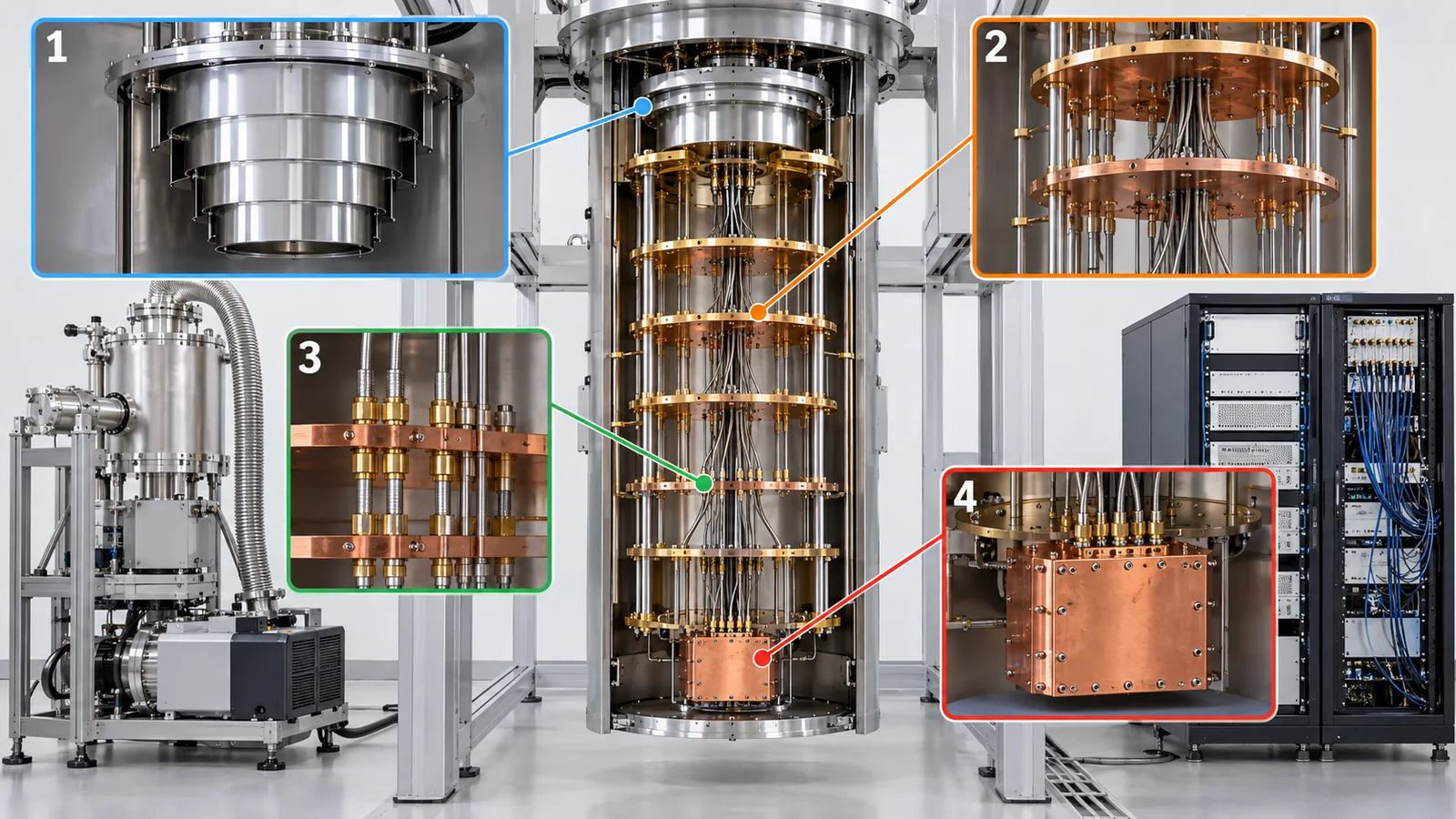
- The short version, what to know first, and where this fits in the series
- Why cool — heat "shakes" a qubit
- How a dilution refrigerator works — five plates, cooling step by step
- Wiring and the heat problem — each line is a path for heat
- Control electronics — from room temperature into the cold
- The scaling wall — beyond thousands of qubits
- A materials engineer's view — materials for refrigerators, wiring and insulation
- What could not be confirmed, and a summary
- How to read evaluations and standards
- Glossary
- References
- Claim-to-source audit
Sourced = stated in published material (source linked)
Our calculation = a value we computed from stated assumptions
Not yet confirmed = company plans, targets and future estimates that are not settled
Our readings and explanations are marked as commentary. An Inference is shown in bold.
The temperatures, cooling powers and heat loads per line are measured values for one particular refrigerator (Bluefors XLD400) and particular lines, reported by Krinner and colleagues in 2018 [Ref. 1]. They are not values of current models and may not match the makers' latest specifications. Line counts and heat flows labelled "our calculation" are simple estimates under stated conditions, not the performance of real machines. Makers' and companies' values are marked "maker's stated value" or "company claim", and we do not rank products. Check date: 16 October 2026.
1. The short version, what to know first, and where this fits in the series
- Why cool: a superconducting qubit's energy corresponds to only about 0.24 K as a temperature (5 GHz). At room temperature (300 K), thermal energy is about 1250 times the qubit's, so the arrow is constantly shaken by heat. So qubits are cooled to about 10 to 20 mK. At 20 mK, the chance that heat excites a 5 GHz qubit is about 6 in a million Our calculation
- How cool: a dilution refrigerator stacks five plates at different temperatures; the bottom one (the mixing chamber) reaches about 6 to 20 mK. But the heat it can remove there is only about 19 microwatts (at 20 mK) [Ref. 1], and even the heat leaking down single wires hits that limit as the wires multiply
- Wiring and scale: more qubits need low-heat wiring materials (NbTi, stainless steel), control circuits that are cooled and placed inside (cryo-CMOS and others), and designs that connect several refrigerators. These are also materials and manufacturing problems
A qubit can be drawn as an "arrow", and you only need to know that heat and other disturbances shake the arrow and destroy the state (decoherence). Temperatures are in kelvin (K), the absolute scale: 0 K is −273.15 °C, and 1 mK is 0.001 K. These are covered in "Quantum Computing Fundamentals" and "Coherence and Fidelity" in this series.
"Quantum Error Correction and the Surface Code" and "Logical Qubits and Fault-Tolerant Quantum Computing" showed that many physical qubits are needed. This article is about the foundation that cools, wires and runs those many qubits. Materials and fabrication of qubits are in "Materials and Fabrication for Quantum Computers", and superconducting qubits themselves in "Superconducting Qubits".
2. Why cool — heat "shakes" a qubit
(1) An everyday example: telling a small ripple on a still lake
Suppose you want to see the small ripple of a pebble dropped in a lake. If a strong wind is churning the surface, you cannot. You have to stop the wind. For a qubit, heat is the wind. A qubit's state is set by a very small energy difference, so if the heat around it jostles strongly, the arrow wanders by itself.
(2) In numbers: a qubit's energy is about 0.24 K in temperature
A superconducting qubit's frequency is typically 5 GHz, and the readout resonator is around 7 GHz [Ref. 1]. The energy gap between a qubit's two states is hν (h is Planck's constant). As a temperature, hν/kB ≈ 0.24 K (5 GHz) Our calculation. Thermal energy at room temperature (about 300 K), kBT, is about 1250 times that (300 ÷ 0.24). So at room temperature heat is far larger than the qubit's energy gap, and the two states mix about half and half.
Let us see the chance that heat excites a qubit with a simple formula. When two states are in thermal equilibrium, the probability of being in the upper one is 1 / (1 + exp(hν/kBT)) (our calculation, for 5 GHz).
| Temperature | Probability of thermal excitation (5 GHz) | Meaning |
|---|---|---|
| 300 K (room temperature) | about 50% | The two states are half and half. No computing possible |
| 2.85 K (4 K stage) | about 48% | Still about half and half |
| 100 mK | about 8.3% | Much lower, but still not enough |
| 50 mK | about 0.8% | Approaching a practical level |
| 35 mK | about 0.1% | The effective temperature measured for one 3D transmon (below) |
| 20 mK | about 6×10⁻⁶ | In ideal thermal equilibrium, almost entirely in the ground state |
Our calculation. Assumes the qubit is in thermal equilibrium at the refrigerator's temperature. Real qubits tend to have a higher "effective temperature" than the refrigerator.
In practice a qubit may not cool all the way to the refrigerator's temperature. Jin and colleagues measured the excited-state population of a 3D transmon while varying the refrigerator temperature. From 35 to 150 mK it followed a Maxwell-Boltzmann distribution in equilibrium with the refrigerator, and below 35 mK it saturated at about 0.1%. They concluded the qubit's effective temperature is 35 mK Sourced [Ref. 3]. Even if the mixing chamber is colder, heat still reaches the qubit, and the likely cause is thermal noise through the wiring and similar paths (our commentary).
(3) Heat also arrives through wiring — thermal photons
Heat comes not only through the refrigerator's plates but also as radio waves travelling down the wires (thermal photons). A hot radio wave in a room-temperature line that reaches the qubit shakes the arrow. The mean number n of thermal photons at 6 GHz is n = 1 / (exp(hν/kBT) − 1): about 1040 at room temperature, about 9 at 4 K, and about 5.6×10⁻⁷ at 20 mK (Our calculation; formula and frequency choice follow Krinner et al. [Ref. 1]). So attenuators are placed in the line to cut thermal photons. To bring the photon number at the qubit down to about 10−3 from a room-temperature line, a total of about 60 dB (a millionth) of attenuation is needed, Krinner et al. explain Sourced [Ref. 1].
A dB is a unit that expresses a ratio of signal sizes on a log scale. 20 dB = one hundredth, 60 dB = one millionth (in power). A 20 dB attenuator passes only 1% of the incoming signal and turns the other 99% into heat [Ref. 1]. So an attenuator both "weakens the signal" and "puts heat into that stage". That is why attenuators are spread over the stages that can take the heat (Section 4).
(4) Different kinds of quantum computer are cooled differently
| Platform | Rough temperature where the qubits sit | What was confirmed |
|---|---|---|
| Superconducting qubits | About 0.01 to 0.02 K (10 to 20 mK) | Krinner et al. ran 50 qubits at 14 mK [Ref. 1] Sourced |
| Silicon spin qubits | 20 mK, and operation above 1 K has also been reported | Operations including a two-qubit logic gate above 1 kelvin [Ref. 12]. A unit cell of two qubits run at about 1.5 K (in isotopically enriched 28Si; single-qubit gate fidelity 98.6%) [Ref. 13]. A cryo-CMOS control chip at 3 K controlled qubits at 20 mK [Ref. 5] Sourced |
| Trapped ions and neutral atoms | Not a refrigerator: atoms or ions in a vacuum are cooled with lasers | IonQ says it traps atoms in three-dimensional space and uses lasers from preparation to readout [Ref. 19]. Quantinuum says ions are held by electromagnetic fields and operated with lasers [Ref. 20] Sourced (company descriptions) |
| Photonic quantum computers | We could not confirm a temperature in primary material | Could not be confirmed |
The arrangement of the table is our commentary. Do not line up temperatures across platforms to rank them.
Not so. Cryogenic refrigerators are needed mainly for solid-state platforms such as superconducting and silicon spin qubits. Trapped ions and neutral atoms are atoms or ions in a vacuum cooled by lasers. And "colder is better" is not always true either. A refrigerator's cooling power falls sharply as temperature drops. Some studies point out that a base temperature of about 10 mK is more than a growing number of systems need, for example as qubit frequencies are raised [Ref. 2]. The right statement is: "decide the temperature you need from the qubit frequency and the error rate you can tolerate".
3. How a dilution refrigerator works — five plates, cooling step by step
(1) An everyday example: five nested rooms
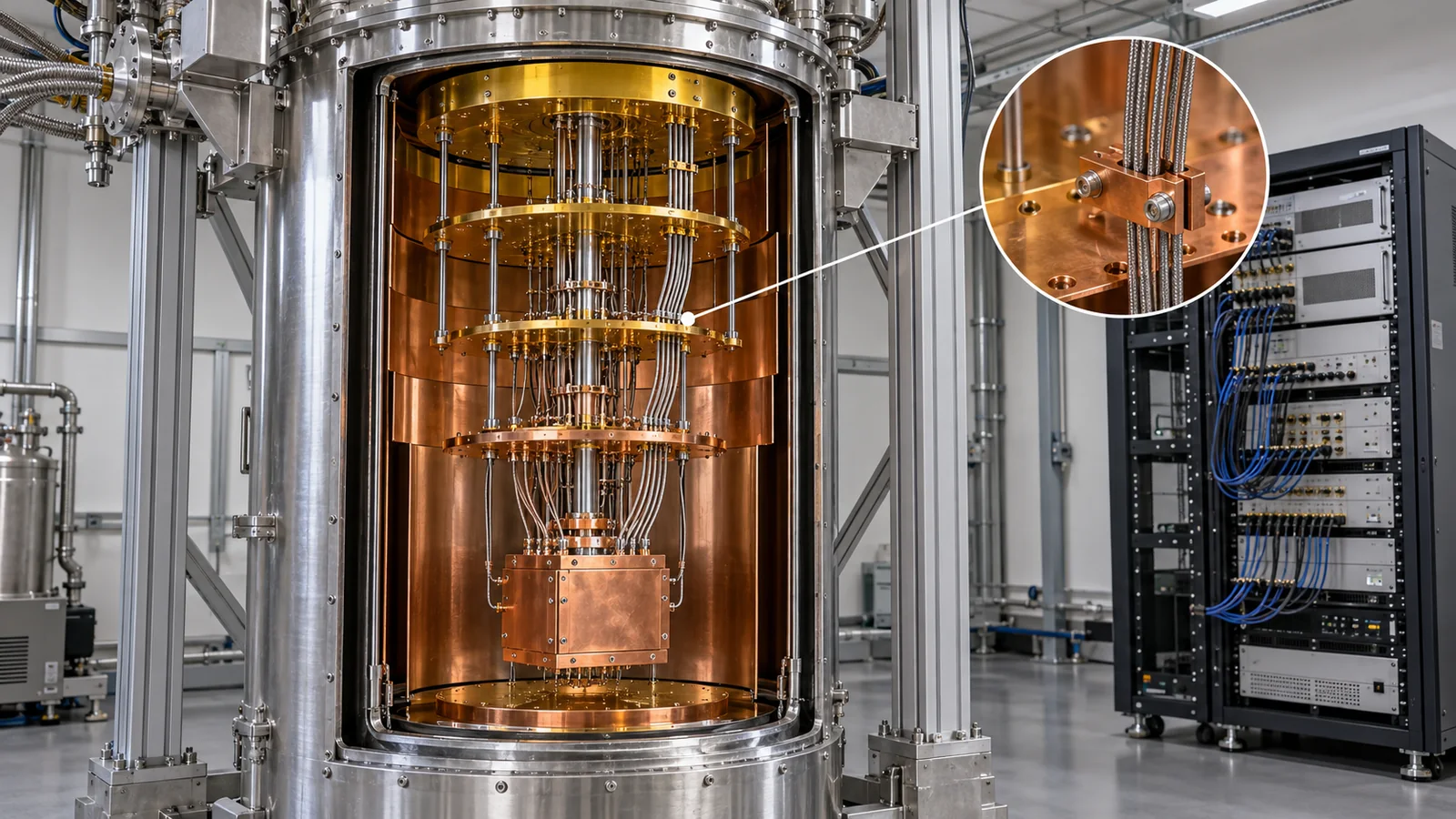
Suppose you nest five rooms to protect an inner room from hot air outside. The outer room is next to the heater, and heat reaches less and less as you go inward. If every room has air conditioning that removes the heat coming in from outside, the innermost room stays very cold. A dilution refrigerator works the same way. Five plates (stages) at different temperatures are stacked on thin rods, and each stage disposes of heat.
View original SVG, values and sources
Original SVG reference: Concept diagram (vector drawing). A concept cross-section of the five stages of a dilution refrigerator. Temperatures and cooling powers are values reported by Krinner et al. (Bluefors XLD400, empty) [Ref. 1], not those of current models.
The figure above shows temperatures of an empty refrigerator, and cooling powers at the stated temperatures, for the Bluefors XLD400 reported by Krinner et al. Sourced [Ref. 1]. The 50 K and 4 K stages are made by pulse-tube coolers (machines that cool through pressure changes of compressed helium gas). The next three stages, the still, the cold plate and the mixing chamber, are the "dilution" part using a mixture of helium-3 and helium-4, and about 6 mK (when empty) at the mixing chamber is the lowest temperature.
(2) The principle of dilution — absorbing heat as helium dissolves
Helium has two isotopes with different masses (helium-3 and helium-4). A liquid mixture of both separates, below about 872 mK, into a helium-3-rich phase and a helium-4-rich phase (the 3He concentration at the point where separation begins is 67.3%) [Ref. 2] Sourced. The lighter 3He-rich phase floats on top, with a boundary between it and the lower phase. In the cold mixing chamber, 3He dissolves from the rich phase into the lower, dilute phase. This absorbs heat from the surroundings. That is "dilution cooling". Dilution refrigerators have been reported to cool continuously down to about 2 mK [Ref. 2].
The 3He that has dissolved into the dilute phase is carried to a slightly warmer chamber called the still and pumped out as gas. It is then compressed, pre-cooled and returned to the rich phase. The 3He circulates in a closed loop and is not used up each time. But 3He is a scarce and costly isotope [Ref. 2]. Bigger refrigerators need more of it, so it could become an important constraint on scaling (our commentary).
(3) The cooling power is very small
The mixing chamber's cooling power (at 20 mK) is about 19 microwatts [Ref. 1]. That is about one 52,000th of a 1 W light bulb (1 / 0.000019 ≈ 52,600; Our calculation). The lower the temperature, the smaller the cooling power. It is about 200 microwatts on the cold plate (at 140 mK), about 40 milliwatts at the still (at 1.2 K), about 1.5 W at the 4 K stage, and about 30 W at the 50 K stage [Ref. 1]. So the heat generated inside the refrigerator (heat conducted down wires, attenuator dissipation, amplifiers, control circuits) must fit within each stage's cooling power.
Most refrigerators for quantum computers today do not. The common design is a "dry" (cryogen-free) one using pulse-tube coolers, with no top-ups of liquid coolant [Ref. 2]. The 3He/4He of the dilution unit also runs in a closed loop. Because cooling is done with electricity (compressors), what weighs on real operation is the refrigerator's power use and the floor space, piping and cooling water (our commentary). The amount of 3He for the initial charge is a separate constraint.
Cooling from 300 K to 10 mK in one go would be inefficient. With stages, heat can be disposed of at the temperature where it can be removed most efficiently, wherever it enters. For example, most of the heat from room-temperature lines is caught at the 50 K and 4 K stages, so little reaches the stages below. The lower stages in the figure have smaller cooling power because the design assumes heat is kept from reaching them.
4. Wiring and the heat problem — each line is a path for heat
(1) An everyday example: small holes in the wall of a winter house
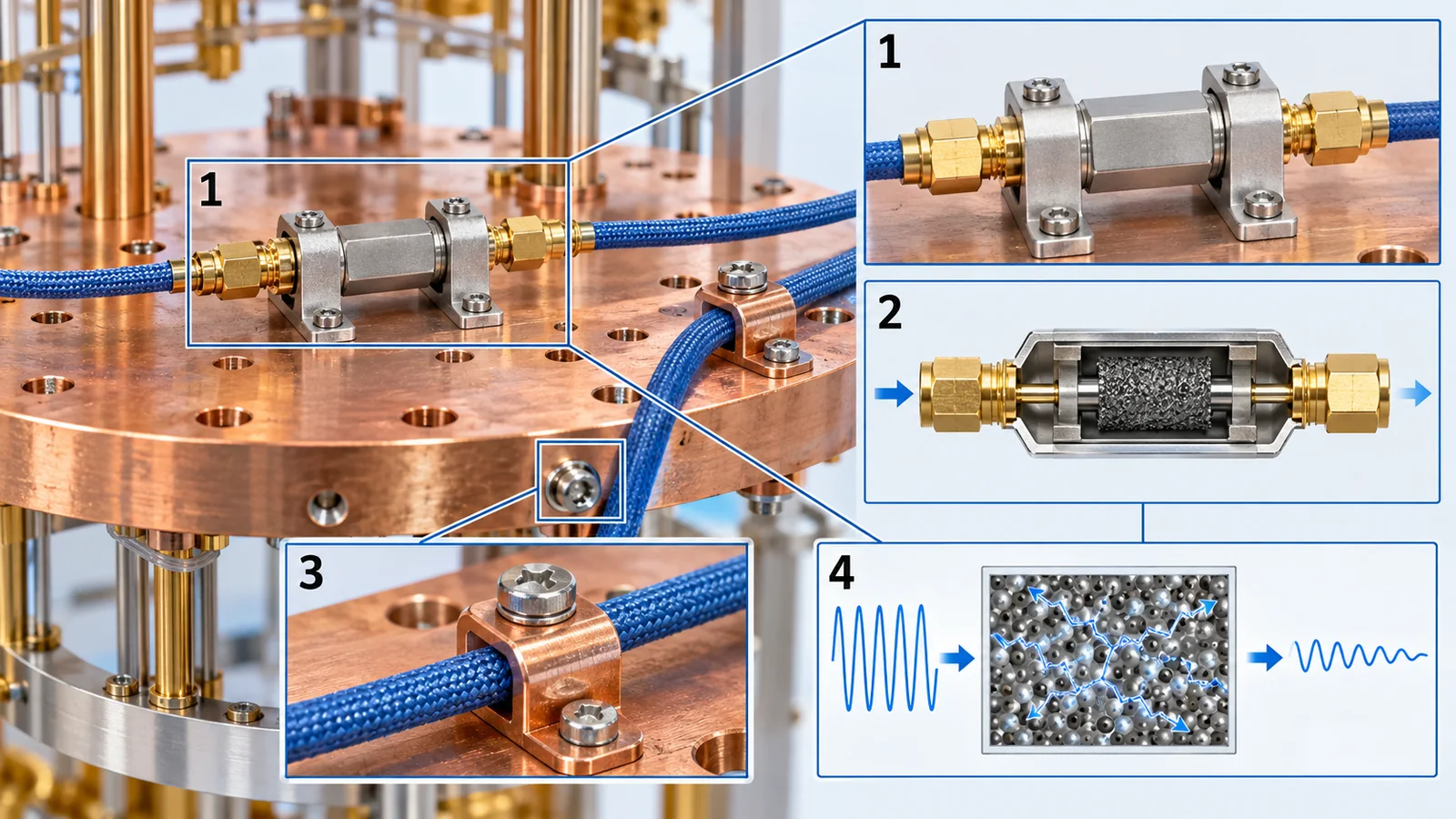
Suppose you drill a small hole in the wall between a warm room and the cold outside. One hole lets in only a little draught. But with hundreds of holes, the heating cannot keep up. The same goes for a cryogenic refrigerator. Every line from room-temperature equipment is a path for heat. Each one carries little, but as their number grows they eat into the limited cooling power.
(2) Types of lines, and the signal path
Experiments with superconducting qubits mainly use three kinds of lines [Ref. 1] Sourced.
- Drive lines: carry the microwaves that operate the qubits
- Flux lines: carry the current that tunes the frequency of a frequency-tunable qubit through magnetic flux
- Output (readout) lines: bring out the qubit's state as a signal from the readout resonator
View original SVG, values and sources
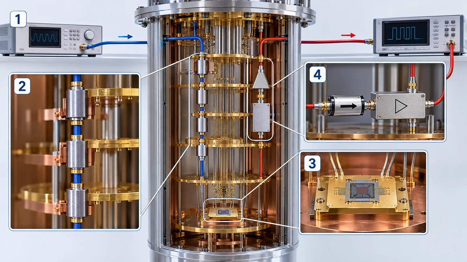
Original SVG reference: Concept diagram (vector drawing). A concept diagram of the parts along the control line (downward) and the readout line (upward) at each temperature stage. The configuration follows the report of Krinner et al. [Ref. 1].
The figure is the configuration adopted by Krinner et al. [Ref. 1]. In the control (drive) line, 20 dB attenuators sit at the 4 K stage, the cold plate and the mixing chamber, for 60 dB in total, to reduce room-temperature thermal photons. In the readout line, a TWPA (travelling-wave Josephson parametric amplifier, a low-noise amplifier near the quantum limit [Ref. 14]) sits at the mixing chamber and a HEMT amplifier (gain about 40 dB) at 4 K. To keep noise from returning to the sample, a circulator and isolators (parts that pass signals in one direction only) give more than 60 dB of isolation in total [Ref. 1] Sourced. To avoid "quasiparticles" (broken Cooper pairs in the superconductor) created by infrared light, an optional infrared filter made of an absorber (Eccosorb CR-124) is provided (6 dB attenuation at 6 GHz, in front of the mixing-chamber attenuator) [Ref. 1].
(3) Passive heat: heat conducted down the lines
A line is made of metal, so it also conducts heat. The heat carried by one line between stages of the refrigerator is "thermal conductivity × cross-section ÷ length" summed over the temperature range (Eq. (1) of Krinner et al.) [Ref. 1]. So materials with low thermal conductivity (stainless steel, superconducting NbTi) are used, thin and long. There is a flip side, though: materials that carry electricity poorly tend to turn signal into heat [Ref. 1]. The heat flowing in per line, as measured by Krinner et al., is as follows Sourced [Ref. 1].
| Type of line | 50 K | 4 K | Still | Cold plate | Mixing chamber |
|---|---|---|---|---|---|
| Drive line (stainless coax UT085 SS-SS) | 45(23) mW | 1.0(2) mW | 4(3) μW | 0.4(2) μW | 0.013(6) μW |
| Flux line (same) | 56(27) mW | 1.2(2) mW | 2(1) μW | 0.29(3) μW | 0.025(5) μW |
| Output line (NbTi coax UT085 NbTi) | — | — | — | 0.29(12) μW | 0.020(16) μW |
Measured values (uncertainty in parentheses). The refrigerator is a Bluefors XLD400, and line lengths between stages are 140 to 290 mm (Tables 1 and 2 of Krinner et al.) [Ref. 1]. The NbTi of the output line is the value for the part that becomes superconducting below 4 K.
From these values and each stage's cooling power, let us compute "how many lines can be run". Dividing a stage's cooling power by the heat flowing in per line gives a rough number of drive lines (Our calculation; passive heat only, not including attenuator dissipation or other lines).
The cold plate (200 μW ÷ 0.4 μW ≈ 500 lines) and the 50 K stage (30 W ÷ 45 mW ≈ 670 lines) hit their limit first. Since several lines are needed per qubit, this combination of refrigerator and line supports a few hundred qubits. Krinner et al. also write that, ignoring space constraints, at least 150 qubits could be operated [Ref. 1].
(4) Active heat: heat from attenuators
An attenuator turns most of the incoming signal into heat (99% for 20 dB) [Ref. 1]. The signal reaching a qubit is tiny (a peak of −66 dBm for a 30 ns π pulse), and on average about −78 dBm is needed at the mixing chamber [Ref. 1]. Even so, a vastly larger signal is sent in at room temperature, so the position and amount of attenuation set how the heat is shared. In an example by Krinner et al., with attenuation split {0, 10, 0, 20, 30} dB (50 K, 4 K, still, cold plate, mixing chamber), the dissipation of 25 drive lines took 35% of the cold plate's cooling power. Removing 10 dB at the cold plate and adding 10 dB at 4 K, to {0, 20, 0, 10, 30} dB, cuts the cold-plate heat to one tenth. In return, the thermal photon number at the qubit side rises from about 0.0012 to 0.002, a bit under double [Ref. 1] Sourced. So where attenuators go is a trade-off between heat and noise.
Every extra qubit adds several lines, and more lines mean more heat. Cooling power is smaller the lower the stage, so the heat reaching the lower stages must be made as small as possible per line. For example, the mixing chamber's cooling power is 19 microwatts [Ref. 1]. If the heat per line grew tenfold, the number of lines that fit would fall to a tenth. Low-conductivity materials, thin wires and heat anchoring (fixing a line thermally to a plate) all count (Section 7).
5. Control electronics — from room temperature into the cold
(1) The present: control equipment at room temperature
The signals that run qubits are made by electronic equipment such as waveform generators, mixers, amplifiers and digitisers. Today the mainstream is to put them in racks at room temperature and send signals to the refrigerator on coaxial lines. An IBM researcher writes that conventional rack-based room-temperature control electronics "impose severe constraints on wiring density, cost and system footprint" and are a barrier to large-scale fault-tolerant computing [Ref. 11] Sourced (a 2026 preprint).
(2) Four ideas for fewer wires
| Idea | Examples and numbers confirmed | Challenges |
|---|---|---|
| B: Cryogenic CMOS (cryo-CMOS) | A control chip running at 3 K controlled silicon qubits at 20 mK with the same fidelity as commercial room-temperature instruments [Ref. 5]. Another chip, running at 100 mK, dissipates 18 nW per control cell, and a system of 1000 cells is estimated to be coolable by a commercial dilution refrigerator [Ref. 7]. A 2026 IBM preprint reports cryo-CMOS circuits running at 7 to 20 K for magnetic-flux control of two-qubit gates on a 156-qubit processor, with gate errors at the 10−3 level (best randomized-benchmarking error 8.4×10⁻⁴) and about one tenth of the footprint [Ref. 11] Sourced | Whether the heat fits the cooling power. The allowed power per qubit is the 4 K stage's 1.5 W ÷ 1000 qubits = about 1.5 mW (our calculation). In Underwood's example, single-qubit control and readout stay at room temperature (a hybrid) |
| C: Optical fibre (photonic link) | Modulated laser light is carried by optical fibre to a cryogenic photodetector to make shot-noise-limited microwave signals at millikelvin. Control and readout of a superconducting qubit were demonstrated [Ref. 8]. The paper says the heat and number of coaxial lines limit a processor to a few thousand qubits Sourced | Heat from the photodetector, optical loss, distributing to many lines |
| D: Superconducting logic (SFQ) | A proposal to place single flux quantum (SFQ) superconducting digital logic as an auxiliary processor near the mixing chamber [Ref. 9]. In a multichip module with the SFQ circuit and qubits on separate chips joined with indium (In) bumps, an error of 1.2(1)% per Clifford gate (a way to suppress quasiparticle generation) [Ref. 10] Sourced | Heat from the circuit creates quasiparticles (broken pairs) that disturb the qubits |
Numbers are as stated in the papers' abstracts. The target qubits (superconducting or silicon) also differ by row. This is not a comparison to rank them.
(3) Why is "heat dissipation" the biggest problem?
A CMOS circuit always gives off heat when it uses electricity. The lower the temperature in the refrigerator, the less heat can be removed, so which stage it goes on is decided by that. Pauka and colleagues noted that CMOS is often discounted because its power dissipation could heat fragile qubits, and showed a chip running at 100 mK with dissipation reduced to 18 nW per cell [Ref. 7] Sourced. In our calculation, dividing the cold plate's 200 μW (at 140 mK; Section 3) by 18 nW gives about 10,000 cells (an upper limit that ignores static power and wiring heat). Xue et al.'s 3 K chip corresponds to being placed at a stage near 4 K (the 4 K stage of Krinner et al.'s refrigerator has about 1.5 W of cooling power [Ref. 1]; the refrigerator is a different one) [Ref. 5].
Part of it is solved, and part remains. A cooled CMOS circuit can reduce the number of high-frequency lines from room temperature to the refrigerator. But new problems arise: the circuit's own heat, digital signal wiring, power lines, and how to cool and mount the circuit inside. The IBM preprint is also a hybrid: only the flux control of two-qubit gates is cryo-CMOS, while single-qubit control and readout remain room-temperature RF circuits [Ref. 11]. The right statement: "the number of lines can be reduced, but there are other walls in heat and packaging".
6. The scaling wall — beyond thousands of qubits
Let us put the above into a sense of scale. The table lists refrigerator examples we could confirm. Makers' stated values and company plans are not achieved facts.
| Example | Cooling power, lines and size | Number of qubits | Category |
|---|---|---|---|
| Bluefors XLD400 (reported 2018) | Cold plate 200 μW (140 mK), mixing chamber 19 μW (20 mK) [Ref. 1] | 50 qubits run at 14 mK. At least 150 estimated to be possible | Measured Sourced |
| Bluefors KIDE (maker's stated value) | Three dilution units, expected over 3000 μW at 100 mK, nine pulse tubes, 1.6 m² base flange, 500 kg payload, over 4000 RF lines [Ref. 15] | Designed to support over 1000 qubits (the maker's description) | Maker's stated value Sourced |
| IBM's modular cryogenic "cell" (August 2026) | About 0.53 m² of wiring area and about 2.75 m³ of vacuum volume per cell. Says two cells were coupled and operated. Built from aluminium panels and framing [Ref. 16] | In future, thousands of qubits per cell expected (a plan) | Company description Sourced. Thousands of qubits: Not yet confirmed |
KIDE's cooling power, according to the maker's page, is measured at the KIDE insert flange. Each company's numbers are under different conditions, so do not line them up to rank them.
Even in a large machine like KIDE, line heat matters. Suppose 4000 lines of the same stainless coax Krinner et al. measured (0.4 μW each at the cold plate) were installed: the passive heat on the cold plate would be 1.6 mW (Our calculation). KIDE's page gives over 3 mW of cooling power at 100 mK, so passive heat alone would use about half. High-density wiring lines have different materials and structures, however, so this calculation is only an example to see the order of magnitude.
Paths to larger scale
- Bigger, and several, refrigerators: IBM shows a modular design with box-shaped "cells" side by side. Putting cells together lets quantum cables pass into the neighbouring cell and joins thermal shielding into a "cold tunnel" that links processors. IBM also says the cells can be used to test "l-couplers" (cables operating inside a dilution refrigerator, at the one-metre scale) [Ref. 16] Not yet confirmed (company plan)
- Fewer lines: cryo-CMOS, SFQ, optical fibre (Section 5)
- Lines that carry less heat: NbTi, thin wires, heat anchoring (Section 7)
- Countering radiation and cosmic rays: radiation creates quasiparticles and limits qubit lifetime. Shielding has been reported to correlate with longer coherence [Ref. 18] Sourced. Materials outside the refrigerator and the installation site are also challenges when scaling up
- Securing 3He: 3He is scarce and costly [Ref. 2]. Our view is that supply limits could appear if large refrigerators multiply (Inference; we did not check supply statistics)
7. A materials engineer's view — materials for refrigerators, wiring and insulation
Cryogenic equipment is full of opportunities for materials engineers. Here we use public property data (NIST fits) to compute how much the heat flow changes with the choice of material.
(1) Heat conduction differs by five orders of magnitude between materials
How readily a material passes heat is its thermal conductivity k (in W/(m·K)). The figure shows thermal conductivity from 4 to 300 K drawn from NIST's fits [Ref. 6] (Our calculation).
What the figure shows (Our calculation):
- Copper (oxygen-free, RRR 100) has a very large thermal conductivity from 4 to 50 K, peaking at about 1540 W/(m·K) at 10 K. Krinner et al. also write that copper has an "anomalously large" thermal conductivity at 4 to 50 K [Ref. 1]. It suits parts that carry heat away (heat anchors, plates) and cannot be used where you want to stop heat
- Stainless steel 304 is about 0.27 W/(m·K) at 4 K and about 15 at 300 K, a thousandth to a few tens of a copper's. It is a poor heat conductor for a metal and is used for the outer conductor of lines and support rods
- G-10, PTFE and polyimide are another one to two orders of magnitude lower (about 0.01 to 0.07 W/(m·K) at 4 K) and suit supports, insulation and thermal spacers
Compare rods of the same shape. The heat flowing through a rod of 1 mm² cross-section and 100 mm length connected from room temperature (300 K) down to 4 K is as follows (NIST's fits integrated over temperature; Our calculation).
| Material | Heat flow (300 K to 4 K) | Ratio to copper |
|---|---|---|
| Copper (RRR 100) | about 1.9 W | 1 |
| Aluminium alloy 6061-T6 | about 0.32 W | about 1/6 |
| Stainless steel 304 | about 30 mW | about 1/64 |
| G-10 (glass epoxy) | about 1.1 mW | about 1/1700 |
| PTFE (Teflon) | about 0.71 mW | about 1/2700 |
| Polyimide (Kapton) | about 0.43 mW | about 1/4500 |
Our calculation. In practice heat is intercepted at stages such as 50 K on the way, so less reaches 4 K. This is an example for comparison. The G-10 values use the normal-direction fit, which applies from 10 K.
The 4 K stage's cooling power was about 1.5 W [Ref. 1]. A copper rod of the same shape connected straight from room temperature to 4 K would by itself exceed that cooling power. The choice of material decides whether a refrigerator can work at all.
(2) Copper's "RRR" — purity and defects set low-temperature conduction
Copper's thermal conductivity depends strongly on RRR (residual resistivity ratio). RRR is the electrical resistance at room temperature divided by that at very low temperature, and is larger the fewer the impurities and crystal defects (the general definition; our commentary). By NIST's fits, the thermal conductivity at 4 K is about 640 W/(m·K) for RRR 100 and about 3180 for RRR 500 (Our calculation) [Ref. 6]. So even for "copper", purity, working and heat treatment can make a fivefold difference in low-temperature performance. When choosing a material for cooling plates and heat anchors, grade and history matter.
(3) Which material for which part
| Part | What is needed | Materials and parts confirmed | Caution |
|---|---|---|---|
| Coaxial lines (RF lines) | Conduct electricity, not heat | Stainless steel coax (UT085 SS-SS). Superconducting NbTi coax below 4 K. CuNi gives 20 to 30% more heat than SS-SS. Copper lines carry a large heat load [Ref. 1] Sourced | NbTi is superconducting only below 4 K, so stainless is used from room temperature to 4 K. Materials that carry electricity poorly tend to turn signal into heat [Ref. 1] |
| DC lines | Thin, poor at conducting heat | Copper or phosphor-bronze twisted pairs from room temperature to 4 K; NbTi twisted pairs from 4 K to the mixing chamber [Ref. 1] Sourced | Copper twisted pairs carry a heat load comparable to coax |
| Attenuators and filters | Cut thermal noise and shed heat | 20 dB attenuators at each stage. A filter using the infrared absorber Eccosorb CR-124 [Ref. 1] Sourced | Attenuators dissipate heat (Section 4). They need good thermal contact |
| Infrared shielding | Keep 4 K blackbody radiation from reaching the qubits | Isolating devices from the radiative environment with multistage shielding removed this contribution to quasiparticle density, reported [Ref. 4] Sourced | The design of an infrared-absorbing filter (Eccosorb CR-124) is described in Appendix C of Krinner et al. [Ref. 1] |
| Cooling plates and heat anchors | Carry heat well | Copper (performance depends on RRR) [Ref. 6] Our calculation | Surface finish and the way of contact change the contact thermal resistance (we could not confirm figures) |
| Supports and spacers | Strong and poor at conducting heat | G-10, PTFE, polyimide and others [Ref. 6] Our calculation | Differences in thermal contraction cause gaps and stress on cooling (our commentary) |
| Refrigerator housing (IBM's cell) | Large, light, easy to machine | Aluminium panels and framing [Ref. 16] Sourced (company description) | Aluminium conducts heat well (see figure). Thermal design of the shielding is needed |
Rows marked "Our calculation" are our calculations from NIST's fits, and rows marked "Sourced" are as stated in each source. The grouping by part is our commentary.
A cryogenic apparatus holds materials whose thermal conductivities differ by five orders of magnitude side by side (copper for plates and heat anchors, stainless steel and NbTi for lines, G-10 and polyimide for supports). Choosing materials is one with the thermal design of what to cool and by how much. Moreover, in metals, electrical and thermal conduction go together (a property close to the Wiedemann-Franz law; our commentary), so a superconductor (NbTi) is especially advantageous for getting a line that "carries electricity but not heat". Krinner et al. also state that materials poor at conducting heat are generally poor at conducting electricity, with superconductors as the exception [Ref. 1]. This is where there is room in choosing materials. For example, a fine-wire material that is superconducting below 4 K and also easy to work, solder and connect is a practical issue that sets the scale of wiring (Inference).
What gets into a refrigerator is not only heat. 4 K blackbody radiation (infrared) increases quasiparticles in a superconductor and shortens qubit lifetimes. Barends and colleagues reported a quasiparticle density of about 200 μm−3, and that separating the device by multistage shielding removes this influence completely [Ref. 4] Sourced. Fluctuations of the magnetic field and magnetic vortices also cause dissipation. Krinner et al. say filters and magnetic shielding can mitigate them [Ref. 1]. Radiation (radioactive materials in the environment and cosmic rays) increases quasiparticles and limits qubit coherence. Introducing shielding has been reported to correlate with longer coherence [Ref. 18]. On the materials side, the absorbing layer (resin and filler that absorb infrared), the magnetic-shield alloy and the radiation-shielding material, and how they are mounted inside the refrigerator, bear directly on qubit lifetime.
The silicon spin-qubit experiment run at 1.5 K used isotopically enriched 28Si (an isotope without nuclear spin), with a coherence time of 2 microseconds [Ref. 13] Sourced. The isotopic purity of the material is one key to a "warm" qubit. A multichip module that joins an SFQ control circuit and the qubits, built on separate chips, with indium (In) bumps suppressed the effect of quasiparticles from the circuit's heat and cut the gate error by about one order of magnitude [Ref. 10] Sourced. It is an example where separating chips, the bonding material and the path of heat decided performance. Cryo-CMOS is an attempt to carry semiconductor manufacturing technology into the cold as it is [Ref. 5, 11]. Understanding how the materials and processes behave at 3 K or 20 K (for example, changes in transistor characteristics) is a premise of design (our commentary).
8. What could not be confirmed, and a summary
What could not be confirmed
- Operating temperature of photonic quantum computers: we could not confirm a number in primary material, so it is not in the table of Section 2.
- Latest specifications of current refrigerators: temperatures and cooling powers are values from the 2018 report (XLD400). Newer models need checking in the makers' official material. KIDE is the maker's stated value.
- Thermal conductivity figures for NbTi: they are not in NIST's tables, so heat flowing down lines uses the measurements of Krinner et al. and no material curve is drawn.
- Contact thermal resistance of heat anchors: important, but we found no figures in the primary material we could check.
- Statistics on 3He supply and price: we confirmed the statement that it is "scarce and costly", but not supply figures.
- Third-party verification of IBM's cryo-CMOS (2026) and modular refrigerator: the former is a preprint (not peer reviewed) and the latter a company blog; we could not confirm independent verification.
- A standard that defines the performance of dilution refrigerators: could not be confirmed (temperature-scale standards are in Section 9).
- Why cool: a 5 GHz qubit is about 0.24 K as a temperature, and room-temperature heat is about 1250 times that. The chance of thermal excitation is about 6×10⁻⁶ at 20 mK and about 8% at 100 mK Our calculation
- The dilution refrigerator: five plates cool step by step, and heat absorbed as helium-3 dissolves into the dilute phase in the mixing chamber makes about 6 to 20 mK. Cooling power at 20 mK is only about 19 μW Sourced
- Wiring: each line is a path for heat. With stainless and NbTi coax, about 500 lines is the guide at the cold plate of that refrigerator, and where attenuators go is a trade-off between heat and noise Sourced / Our calculation
- Control electronics: cryo-CMOS (3 to 20 K), optical fibre and SFQ are being tried to cut lines. But heat and packaging remain other walls Sourced
- For materials engineers: thermal conductivity differs by five orders of magnitude between materials. Copper (RRR), stainless steel, NbTi, polymers, absorbing and shielding materials, isotope-purified silicon and bonding materials hold the key to scaling up Our calculation
9. How to read evaluations and standards
The yardsticks of cryogenics and control are the base temperature, the cooling power at a stated temperature, the heat load per line, a qubit's effective temperature (excited-state population) and the number of thermal photons. None has meaning unless you state the temperature and where it was measured (which stage). We could not confirm a standard that defines refrigerator performance. There is, however, an international standard for the temperature scale itself at cryogenic temperatures. Check date: 16 October 2026.
| Item evaluated | Representative benchmark or method (name and source) | Standards and guidance (ISO/IEC, BIPM and others) | Cautions in reading |
|---|---|---|---|
| Base temperature | Mixing chamber of an empty refrigerator: 6 mK; in operation: 14 mK (Krinner et al.) [Ref. 1] Sourced | PLTS-2000 (Provisional Low Temperature Scale): adopted by the CIPM in October 2000 to extend ITS-90 to lower temperatures. Based on the melting pressure of 3He, 0.902 mK to 1 K (BIPM realisation guide) [Ref. 17] Sourced | Is it "empty" or "loaded", and which thermometer? A thermometer's calibration traces to a scale such as PLTS-2000 |
| Cooling power | A value at a stated temperature. Cold plate 200 μW (140 mK), mixing chamber 19 μW (20 mK) [Ref. 1]. KIDE: over 3000 μW expected at 100 mK (maker's stated value) [Ref. 15] Sourced | Could not be confirmed | Check where it was measured (for example at the insert flange) and the temperature. Do not line up values at different temperatures |
| Heat load per line | Measured passive heat flow at each stage (stainless coax: mixing chamber 0.013 μW, cold plate 0.4 μW and so on) [Ref. 1] Sourced | Could not be confirmed (material property data are NIST's "Cryogenic Material Properties"; reference data, not a standard) [Ref. 6] | Depends on the type and length of line and the way of heat anchoring |
| Qubit effective temperature | Measuring the excited-state population against temperature. 3D transmon: effective temperature 35 mK, population saturating at about 0.1% (Jin et al.) [Ref. 3] Sourced | Could not be confirmed | Different from the refrigerator's temperature. It rises with thermal noise in wiring and with quasiparticles |
| Number of thermal photons | An index for designing line attenuation. 6×10⁻⁷ at 6 GHz and 20 mK; about 10−3 for a room-temperature line with 60 dB attenuation (Krinner et al.) [Ref. 1] Sourced | Could not be confirmed | State the frequency and temperature. Note that attenuators add thermal noise at each stage's temperature |
| Terms | — (a terminology standard rather than an evaluation) | ISO/IEC 4879:2024 "Information technology — Quantum computing — Vocabulary" (published May 2024; text is paid) [Ref. 21] Sourced | A standard for aligning definitions; it does not set how to measure refrigerator performance. The text was not checked |
| Standard for performance metrics and benchmarking | — | The site of the IEEE P7131 working group (a draft standard) [Ref. 22] Not yet confirmed | At the draft stage. Publication status could not be confirmed |
The arrangement of the table is Our calculation (organising). Numbers, titles and adoption dates of standards were checked on each body's page (check date 16 October 2026). Standards texts are paid, so only titles and scope are given.
Cautions in reading (for materials engineers)
- "Lowest temperature of the refrigerator" and "temperature of the qubit" are different: even with a 6 mK mixing chamber, a qubit's effective temperature may be 35 mK. Read cooling power together with the temperature
- Makers' stated values differ in where and how they are measured: KIDE's value is stated as measured "at the insert flange". Do not line it up against other makers or models to rank them
- Company announcements and third-party verification are different: IBM's cryo-CMOS is a non-peer-reviewed preprint and the modular refrigerator is a company blog. They are treated as "company claims"
- Standards are at the stage of temperature scales and terms: PLTS-2000 is an international scale for how to measure temperature; it does not decide pass or fail on a refrigerator's performance or safety. ISO/IEC 4879 is a terminology standard with no legal force (in general a standard becomes binding when cited in law or a contract; our commentary)
10. Glossary
- Kelvin (K)
- The unit of absolute temperature. 0 K = −273.15 °C. 1 mK = 0.001 K.
- Dilution refrigerator
- A machine that cools to millikelvin using a mixture of helium-3 and helium-4.
- Pulse-tube cooler
- A machine that makes about 50 K and 4 K using pressure changes of helium gas.
- Stage
- A plate at a given temperature inside the refrigerator: 50 K, 4 K, still, cold plate, mixing chamber.
- Mixing chamber
- The coldest part, where 3He dissolves into the dilute phase to cool.
- 3He / 4He
- The two isotopes of helium. 3He is scarce and costly.
- Phase separation
- The mixture splitting, below about 872 mK, into a 3He-rich and a dilute phase.
- Cooling power
- The amount of heat (W) that can be removed at a given temperature. Smaller at lower temperatures.
- Passive heat
- Heat that flows in from upper stages through lines and supports.
- Active heat
- Heat given off by signals and electronics (attenuators, amplifiers, control circuits).
- Thermal photon
- A particle of radio wave made by heat. Too many disturb a qubit.
- Attenuator
- A part that weakens a signal. It also cuts thermal noise but gives off heat.
- dB (decibel)
- A log ratio. 20 dB = a hundredth, 60 dB = a millionth.
- HEMT
- High-electron-mobility transistor. A low-noise amplifier used at 4 K.
- TWPA
- Travelling-wave Josephson parametric amplifier. A low-noise amplifier used at the mixing chamber.
- Circulator / isolator
- Parts that pass signals in one direction only.
- NbTi
- A niobium-titanium alloy. Superconducting below 4 K and a poor heat conductor; used for lines.
- Thermal conductivity
- How well a material passes heat (W/(m·K)).
- RRR
- Residual resistivity ratio. A measure of copper's purity and few defects; larger means better heat conduction at low temperature.
- Heat anchor
- Fixing a line or part thermally to a cold plate to shed heat.
- Quasiparticle
- A broken pair in a superconductor. Created by infrared and radiation, and disturbs qubits.
- Cryo-CMOS
- CMOS circuits operated at cryogenic temperature; putting control inside the refrigerator.
- SFQ
- Single flux quantum. Digital logic built from superconductors.
- PLTS-2000
- A provisional temperature scale from 0.902 mK to 1 K, based on the melting pressure of 3He.
11. References
- Krinner S. et al. "Engineering cryogenic setups for 100-qubit scale superconducting circuit systems", EPJ Quantum Technology 6, 2 (2019), DOI 10.1140/epjqt/s40507-019-0072-0 (arXiv:1806.07862) — doi.org/10.1140/epjqt/s40507-019-0072-0
- Kim P. H. et al. "A continuously-cooled 3He/4He phase separation refrigerator", arXiv:2503.10754 (2025) (preprint) — arxiv.org/abs/2503.10754
- Jin X. Y. et al. "Thermal and residual excited-state population in a 3D transmon qubit", Phys. Rev. Lett. 114, 240501 (2015), DOI 10.1103/PhysRevLett.114.240501 — doi.org/10.1103/PhysRevLett.114.240501
- Barends R. et al. "Minimizing quasiparticle generation from stray infrared light in superconducting quantum circuits", Appl. Phys. Lett. 99, 113507 (2011), DOI 10.1063/1.3638063 — doi.org/10.1063/1.3638063
- Xue X. et al. "CMOS-based cryogenic control of silicon quantum circuits", Nature 593, 205–210 (2021), DOI 10.1038/s41586-021-03469-4 — doi.org/10.1038/s41586-021-03469-4
- NIST "Cryogenic Material Properties" (fits for thermal conductivity and other properties; checked 16 October 2026) — trc.nist.gov/cryogenics/materials/materialproperties.htm
- Pauka S. J. et al. "A cryogenic CMOS chip for generating control signals for multiple qubits", Nature Electronics 4, 64–70 (2021), DOI 10.1038/s41928-020-00528-y — doi.org/10.1038/s41928-020-00528-y
- Lecocq F. et al. "Control and readout of a superconducting qubit using a photonic link", Nature 591, 575–579 (2021), DOI 10.1038/s41586-021-03268-x — doi.org/10.1038/s41586-021-03268-x
- McDermott R. et al. "Quantum–classical interface based on single flux quantum digital logic", Quantum Sci. Technol. 3, 024004 (2018), DOI 10.1088/2058-9565/aaa3a0 — doi.org/10.1088/2058-9565/aaa3a0
- Liu C.-H. et al. "Single flux quantum-based digital control of superconducting qubits in a multichip module", PRX Quantum 4, 030310 (2023), DOI 10.1103/PRXQuantum.4.030310 — doi.org/10.1103/PRXQuantum.4.030310
- Underwood D. et al. (IBM Quantum) "Transistors to transmons: large-scale cryogenic CMOS control of superconducting qubits", Research Square preprint (3 July 2026) (not peer reviewed) — doi.org/10.21203/rs.3.rs-10095152/v1
- Petit L. et al. "Universal quantum logic in hot silicon qubits", Nature 580, 355–359 (2020), DOI 10.1038/s41586-020-2170-7 — doi.org/10.1038/s41586-020-2170-7
- Yang C. H. et al. "Operation of a silicon quantum processor unit cell above one kelvin", Nature 580, 350–354 (2020), DOI 10.1038/s41586-020-2171-6 — doi.org/10.1038/s41586-020-2171-6
- Macklin C. et al. "A near–quantum-limited Josephson traveling-wave parametric amplifier", Science 350, 307–310 (2015), DOI 10.1126/science.aaa8525 — doi.org/10.1126/science.aaa8525
- Bluefors "KIDE Cryogenic Platform" (maker's product page; checked 16 October 2026) — bluefors.com/products/kide-cryogenic-platform/
- IBM "IBM's new modular architecture for cryogenic systems", IBM Quantum blog (19 August 2026) (company description) — ibm.com/quantum/blog/modular-cryogenics
- BIPM "Supplementary Information for the Realization of the PLTS-2000" (CCT realisation guide) — bipm.org/…/Guide-PLTS-2000.pdf
- Vepsäläinen A. P. et al. "Impact of ionizing radiation on superconducting qubit coherence", Nature 584, 551–556 (2020), DOI 10.1038/s41586-020-2619-8 — doi.org/10.1038/s41586-020-2619-8
- IonQ "IonQ roadmap" (official page; checked 16 October 2026) — ionq.com/roadmap
- Quantinuum "Technical perspective: By the end of the decade, we will deliver universal, fully fault-tolerant quantum computing", official blog (September 2024) — quantinuum.com/blog/technical-perspective…
- ISO/IEC 4879:2024 "Information technology — Quantum computing — Vocabulary" (published May 2024). Number, title, date and "Published" status were checked on the listing page of the Institute for Standardization of Serbia (ISS) — iss.rs/en/project/show/iso:proj:80432 (the official ISO page is https://www.iso.org/standard/80432.html; it could not be fetched automatically from our environment, and was confirmed through search-result listings)
- IEEE P7131 working group "Quantum Benchmarking Working Group P7131" (site of the working group on the draft standard for quantum computing performance metrics and benchmarking) — sagroups.ieee.org/7131
12. Claim-to-source audit
| Claim in the text | Basis | Label |
|---|---|---|
| Stage temperatures of a Bluefors XLD400 (35 K, 2.85 K, 0.882 K, 82 mK, 6 mK) and cooling powers (30 W, 1.5 W, 40 mW, 200 μW, 19 μW at 45 K, 4.2 K, 1.2 K, 140 mK and 20 mK). 50 qubits run at 14 mK; at least 150 qubits estimated possible | Table 1 and text of Krinner et al. (2019) Reference 1 https://doi.org/10.1140/epjqt/s40507-019-0072-0 | Sourced |
| Qubits at 5 GHz and readout at 7 GHz. The thermal-photon formula; about 60 dB of attenuation for a photon number of 10−3 from a room-temperature line; 6×10⁻⁷ at 20 mK and 6 GHz. A 20 dB attenuator turns 99% of the signal into heat | Section 2 of Krinner et al. (2019) Reference 1 https://doi.org/10.1140/epjqt/s40507-019-0072-0 | Sourced |
| The line configuration for drive, flux and output lines (20 dB × 3, Eccosorb CR-124 filter, TWPA, HEMT of about 40 dB, 60 dB or more from circulator and isolators). The trade-off in attenuation splits C1 and C2 (cold-plate load 35% to about a tenth, photon number 0.0012 to 0.002) | Section 3 of Krinner et al. (2019) Reference 1 https://doi.org/10.1140/epjqt/s40507-019-0072-0 | Sourced |
| Measured passive heat load per line (stainless coax: 50 K 45(23) mW, 4 K 1.0(2) mW, still 4(3) μW, cold plate 0.4(2) μW, mixing chamber 0.013(6) μW; NbTi output line: 0.29(12) μW, 0.020(16) μW). CuNi 20 to 30% above SS-SS. Copper has large thermal conductivity at 4 to 50 K | Table 2 and Section 2 of Krinner et al. (2019) Reference 1 https://doi.org/10.1140/epjqt/s40507-019-0072-0 | Sourced |
| 3He/4He phase separation below about 872 mK (3He 67.3%); dilution refrigerators cool continuously down to about 2 mK; 3He is scarce and costly; dry (pulse-tube) refrigerators; about 10 mK for a dry dilution refrigerator, more than some systems need | Introduction and Section 2 of Kim et al. (preprint, 2025) Reference 2 https://arxiv.org/abs/2503.10754 | Sourced |
| Excited-state population of a 3D transmon: equilibrium from 35 to 150 mK, saturating at about 0.1% below 35 mK, effective temperature 35 mK | Abstract of Jin et al. (2015) Reference 3 https://doi.org/10.1103/PhysRevLett.114.240501 | Sourced |
| Quasiparticle density of about 200 μm−3 from 4 K blackbody radiation; multistage shielding removes the influence completely | Abstract of Barends et al. (2011) Reference 4 https://doi.org/10.1063/1.3638063 | Sourced |
| A 3 K cryo-CMOS control chip controlled silicon qubits at 20 mK with the same fidelity as commercial room-temperature instruments | Abstract of Xue et al. (2021) Reference 5 https://doi.org/10.1038/s41586-021-03469-4 | Sourced |
| A 100 mK CMOS chip, 18 nW per cell, an estimate that 1000 cells can be cooled by a commercial dilution refrigerator | Abstract of Pauka et al. (2021) Reference 7 https://doi.org/10.1038/s41928-020-00528-y | Sourced |
| IBM's cryo-CMOS (7 to 20 K, 156 qubits, errors at the 10−3 level, best 8.4×10⁻⁴, about one tenth of the footprint, a hybrid configuration) (a company preprint) | Abstract of Underwood (July 2026, not peer reviewed) Reference 11 https://doi.org/10.21203/rs.3.rs-10095152/v1 | Sourced |
| Control and readout through an optical-fibre photonic link; the statement that the heat and number of coaxial lines limit a processor to a few thousand qubits | Abstract of Lecocq et al. (2021) Reference 8 https://doi.org/10.1038/s41586-021-03268-x | Sourced |
| A proposal to place SFQ logic as a coprocessor near the mixing chamber. A multichip module (In bumps) that suppresses the effect of quasiparticles, with 1.2(1)% error per Clifford gate | Abstracts of McDermott et al. (2018) and Liu et al. (2023) Reference 9 https://doi.org/10.1088/2058-9565/aaa3a0 Reference 10 https://doi.org/10.1103/PRXQuantum.4.030310 | Sourced |
| Operations including two qubits above 1 K in silicon quantum dots. At about 1.5 K, using 28Si, a single-qubit gate fidelity of 98.6% and a coherence time of 2 microseconds | Abstracts of Petit et al. (2020) and Yang et al. (2020) Reference 12 https://doi.org/10.1038/s41586-020-2170-7 Reference 13 https://doi.org/10.1038/s41586-020-2171-6 | Sourced |
| The TWPA is a near-quantum-limited travelling-wave Josephson parametric amplifier | Title of Macklin et al. (2015) Reference 14 https://doi.org/10.1126/science.aaa8525 | Sourced |
| Bluefors KIDE: three dilution units, over 3000 μW expected at 100 mK, over 4000 RF lines, 1.6 m², 500 kg, over 1000 qubits (maker's stated values) | Bluefors product page Reference 15 https://bluefors.com/products/kide-cryogenic-platform/ | Sourced |
| IBM's modular cryogenic cell (about 0.53 m² of wiring area, about 2.75 m³ of vacuum, aluminium panels, two cells coupled and operated, thousands of qubits per cell in future, l-couplers) | IBM Quantum blog (19 August 2026) Reference 16 https://www.ibm.com/quantum/blog/modular-cryogenics | Not yet confirmed |
| PLTS-2000: adopted by the CIPM in October 2000, based on the melting pressure of 3He, 0.902 mK to 1 K | BIPM realisation guide Reference 17 https://www.bipm.org/documents/20126/41773843/Guide-PLTS-2000.pdf/43f543da-0a62-2677-fc38-c8ab70d0539a?version=1.3&t=1593071972719&download=true | Sourced |
| Increase in quasiparticles from environmental radioactive materials and cosmic rays; correlation of shielding with longer coherence | Abstract of Vepsäläinen et al. (2020) Reference 18 https://doi.org/10.1038/s41586-020-2619-8 | Sourced |
| The descriptions by IonQ and Quantinuum that atoms and ions are operated with lasers | The companies' official material Reference 19 https://www.ionq.com/roadmap Reference 20 https://www.quantinuum.com/blog/technical-perspective-by-the-end-of-the-decade-we-will-deliver-universal-fault-tolerant-quantum-computing | Sourced |
| Fits of thermal conductivity (copper RRR 50 to 500, aluminium 6061-T6, stainless 304, G-10, PTFE, polyimide). The fit range is 4 to 300 K (G-10 from 10 K) | NIST Cryogenic Material Properties Reference 6 https://trc.nist.gov/cryogenics/materials/materialproperties.htm | Sourced |
| ISO/IEC 4879:2024 "Information technology — Quantum computing — Vocabulary" was published in May 2024 | Listing page of the Institute for Standardization of Serbia (ISS) Reference 21 https://iss.rs/en/project/show/iso:proj:80432 | Sourced |
| The IEEE P7131 working group has a draft standard for quantum computing performance metrics and benchmarking as its technical scope. Publication status could not be confirmed | The working group's site Reference 22 https://sagroups.ieee.org/7131 | Not yet confirmed |
| hν/kB of about 0.24 K (5 GHz); the table of thermal-excitation probability (about 50% at 300 K, about 6×10⁻⁶ at 20 mK); thermal photon numbers (about 1040 at room temperature, 9.4 at 4 K, 0.03 at 82 mK, 5.6×10⁻⁷ at 20 mK); 19 μW is about one 52,000th of 1 W; guide numbers of lines (cold plate about 500, 50 K about 670, 4 K about 1500, mixing chamber about 1460, still about 10,000); the cold plate's 200 μW ÷ 18 nW = about 10,000 cells; 4 K's 1.5 W ÷ 1000 = about 1.5 mW; 4000 lines × 0.4 μW = 1.6 mW; heat through rods (copper 1.9 W, aluminium 0.32 W, stainless 30 mW, G-10 1.1 mW, PTFE 0.71 mW, polyimide 0.43 mW) and the ratios to copper; thermal conductivity at 4 K for RRR 100 and 500 (about 640 and 3180 W/(m·K)) | Our calculation (Python. Uses NIST's fits and the values and formula of Krinner et al.; assumptions stated in the text). Not results from a real machine | Our calculation |
| The operating temperature of photonic quantum computers, the latest specifications of current refrigerators, thermal conductivity figures of NbTi, contact thermal resistance of heat anchors, statistics on 3He supply, third-party verification of cryo-CMOS and modular refrigerators, a standard defining refrigerator performance, the text of ISO/IEC 4879, the publication status of IEEE P7131 | Not described, because they could not be confirmed in the primary material available within the scope of this research | Commentary |
| The analogies of "ripples on a lake", "holes in a wall" and "five nested rooms", and the readings "copper grade changes low-temperature performance", "materials that carry electricity poorly turn signal into heat", "the material of superconducting lines sets scale", and "understanding how semiconductor-process materials behave in the cold is needed" | Our organisation and commentary based on published content. Not views stated by the bodies concerned | Commentary |
| Fig. 1 and Fig. 6 are ImageGen-generated conceptual illustrations. The other figures are explanatory drawings, not observations of real data | Note in this article | Commentary |
Last updated 16 October 2026. Sources are limited to primary material (peer-reviewed papers, arXiv papers, official pages of NIST and BIPM, official material from refrigerator makers, IBM, IonQ and Quantinuum, and ISO standard listing pages). Makers' stated values, company descriptions and plans are kept separate. Most temperatures and cooling powers are values for one refrigerator reported in 2018, not for current models. Numerical estimates are our own calculations, not results from real machines. The operating temperature of photonic quantum computers, the latest refrigerator specifications, thermal conductivity figures of NbTi, contact thermal resistance of heat anchors, statistics on 3He supply, third-party verification of cryo-CMOS and modular refrigerators, a standard defining refrigerator performance, the text of ISO/IEC 4879 and the publication status of IEEE P7131 could not be confirmed and are not stated here. All figures are explanatory concept diagrams or drawings that include our calculations; Fig. 1 and Fig. 6 are ImageGen-generated conceptual illustrations.