

Key Findings
The developed system enables automated molecular diagnostics by combining centrifugal microfluidic discs with a computer-vision-based detection module. The system utilizes AruCo markers as references to identify detection chambers and measure RGB values to determine whether a sample is positive or negative based on defined thresholds.
Technical Details
The centrifugal disc consists of three layers: a 2 mm thick clear PMMA top disc, a 50 µm thick double-sided pressure sensitive adhesive (PSA) middle layer, and a 0.5 mm thick clear PMMA bottom disc. The top layer includes a round loading chamber, a venting channel, and a bead loading column. The middle layer contains the fluid flow channel connecting the loading and detection chambers. These components are fabricated using a Roland Modela MDX-40A CNC milling machine and a Graphtec CE6000-40 cutter plotter.
For sample processing, NBNM agarose beads (Capto Adhere, Cytiva) are packed into the discs. The process involves diluting the bead resin stock in DI-water at 20% (v/v), adding 20 µL to the bead chamber, and dehydrating the beads in a vacuum chamber (15 Pa, 10 min) using a Femto Science CUTE.
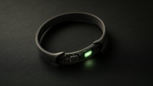
The heating module is a custom ring-shaped aluminum PCB (outer diameter 120 mm, inner diameter 75 mm) that employs joule heating. It features a conductor 4288 mm long and 1 mm wide with a resistance of 3.2 Ω and a cross section of 0.03 mm². At a supply voltage of 12V, it has a power dissipation of 43W. Temperature is managed via a MOSFET and a PID control algorithm.
Signal Acquisition and Readout
The readout system employs a Raspberry Pi 4 and a Raspberry Pi Camera Module 2 with an 8-megapixel sensor. A Kapton (polyimide) film is applied to the sensor to serve as an emission filter for fluorescence imaging. The computer vision algorithm identifies the detection chamber via AruCo markers to perform the final RGB value measurement.
Source: https://doi.org/10.21203/rs.3.rs-11174292/v1
Get our weekly technology intelligence — free
Receive an infographic that lets you judge at a glance whether each field’s analysis report is worth reading.
Subscribe Free — Weekly Tech Intelligence
By subscribing, you’ll receive Troy-Technical’s weekly technology intelligence newsletter.
- Your email and selected fields are used only to deliver the newsletter.
- We never share your information with third parties.
- You can unsubscribe anytime via the link in each email.
See our Privacy Policy for details.
Takes about a minute · Unsubscribe anytime