TROY TECHNICAL · BEGINNER’S GUIDE
READ THIS FIRSTPerovskite solar cells — An Introduction
What can a thin solar absorber enable? A picture wider than efficiency alone.
Japanese version →What if solar generation could reach places that cannot easily carry heavy panels? Interest in perovskite solar cells combines new installation possibilities with the prospect of using sunlight more effectively. Achieving either requires more than a light absorber: charge extraction, protection and repeatable manufacturing matter too.
01The name describes a crystal structure, not one element
Perovskite names a crystal structure. Solar absorbers commonly use metal-halide compositions, whose constituent elements can be adjusted to alter their optical properties. Not every material with a perovskite structure is a suitable solar absorber.
One attraction is a very thin active layer. But a thin absorber does not automatically make the finished product lightweight or flexible. Some devices use glass; flexible versions require electrodes and protection that also tolerate bending.
Background: [1]
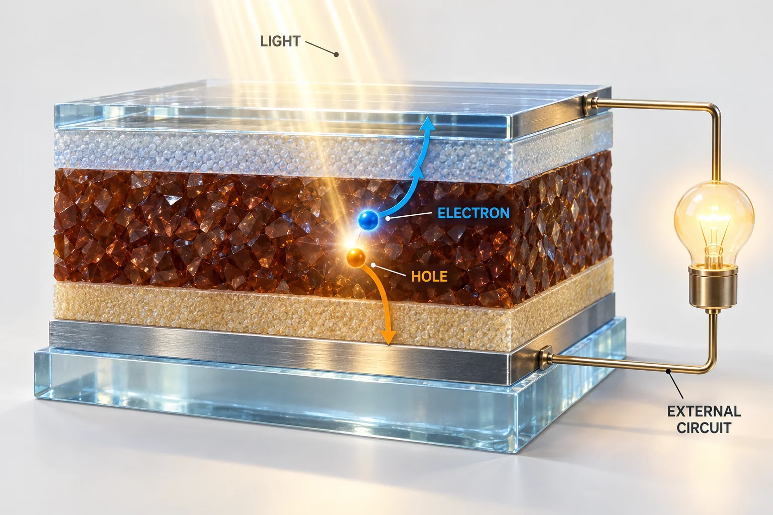
02Absorbing light is only the beginning
Absorbed light creates mobile charge carriers: electrons and holes. A hole represents a missing electron behaving as a positive charge. If the carriers recombine before collection, they do not supply useful power to an external device.
Selective layers and contacts help collect the two types of carrier. An external circuit then receives electrical power. Passivation and interface engineering seek to reduce losses along this path. They do not create extra energy; the energy source remains incoming light.
03A thin-film device or a partner for silicon
A single-absorber device puts emphasis on installation possibilities, mass and processes such as coating. A tandem combines two solar cells that use different parts of the spectrum, allowing the lower cell to use some light transmitted by the upper one.
The two efficiencies cannot simply be added. The upper cell can block useful light, and connections introduce losses. Optical design and electrical matching must be considered together. Perovskites can therefore complement silicon, not merely compete to replace it.
Background: [1]

04A small-cell efficiency is not an outdoor energy yield
A small laboratory cell, an interconnected module and an outdoor installation measure different levels of a system. Larger areas introduce coating variation, defects and space for wiring, edges and protection. Illumination, temperature and ageing add further differences.
Read efficiency together with measurement area, conditions, independent confirmation and whether power is stabilized at an operating point. For durability, inspect heat, humidity, light and electrical conditions, not test duration alone. An accelerated test is not automatically equivalent to a stated number of outdoor years.
Background: [3]
05Protection and end-of-life belong in the design
Moisture, oxygen, heat, light and ion movement within the material can contribute to degradation. Protection must include edges and electrical exits, not just a cover over the surface. The composition giving the highest initial efficiency need not give the best service stability.
Lead-containing compositions also require plans to limit release if damaged and to collect and manage material at end of life. Lead-free alternatives have their own challenges. The useful question is not simply whether a cell is light or efficient, but whether a complete product can perform its intended role throughout its lifecycle.
Background: [1]
Connect the ideas in one situation
ILLUSTRATIVE SCENARIO — NOT A PERFORMANCE CLAIM
Suppose the goal is a lightweight roof installation
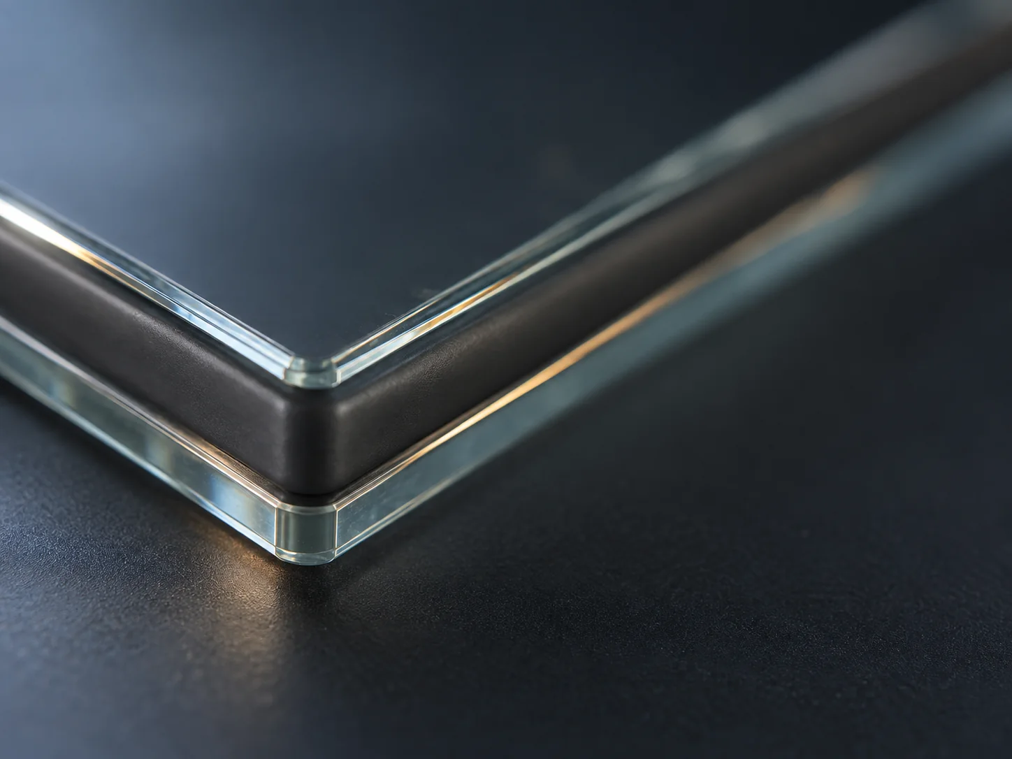
Count the support, electrodes, protection, wiring and mounting hardware as well as the thin absorber. If the surface bends, test electrical function and protection after bending.
The design question is reliable energy from that roof, not simply the highest small-cell efficiency. Lightweight devices and conventional silicon panels can serve different installations.
Return to the starting idea
A thin semiconductor absorbs light and releases useful charge. Assess the opportunities in weight and efficiency together with durability, manufacturing and environmental controls.
You do not need to memorize every technology name. Understanding the intended improvement, the mechanism being changed and the conditions needed to demonstrate it gives you a foundation for the detailed articles. Choose one route that matches your question.
Choose your next article
Read a route from top to bottom, or select just the question you need. You do not have to read everything.
Understand conversion
Explore films and manufacturing
Read performance and lifetime claims
Browse all technical articles in this field (18)
- Ion Migration and Degradation
- Perovskite-Silicon Tandems
- Tin-Based Perovskites
- Bandgap and Composition Design
- Passivation
- Flexible Perovskite Solar Cells
- Perovskite Basics
- Roll-to-Roll Processing and Scale-Up
- All-Perovskite Tandems
- Levelized Cost of Electricity (LCOE)
- Solution Coating
- Conversion Efficiency and Performance Metrics
- Encapsulation and Barrier Layers
- Outdoor Testing and Durability Assessment
- Self-Assembled Monolayers (SAMs)
- Transparent Conductive Oxides (ITO, IZO, FTO)
- Lead and Iodine
- Charge Transport Layers and Cell Architecture
Sources and scope
This introductory synthesis connects the existing technical articles. Its grouping and design scenarios are explanatory, not standard classifications or test results. It does not catalogue current records, product availability or approvals, or forecast costs. Foundational references are below; linked articles provide more detailed technical sourcing.