


Key Findings
The Gas-FE method achieved a measured growth rate of approximately 18.6 nm/s, or roughly 1.1 µm per minute. Using methylammonium lead iodide (MAPbI₃) with 10 mol% methylammonium chloride and 8 mol% lithium TFSI, the team deposited films ranging from 100 to 1,100 nm in thickness by adjusting powder injection times between 7 and 60 seconds. On a 10 × 10 cm² substrate, the I:Pb ratio varied by less than 5% and film thickness by 4%, with run-to-run variation between 6% and 8%.
Technical Details
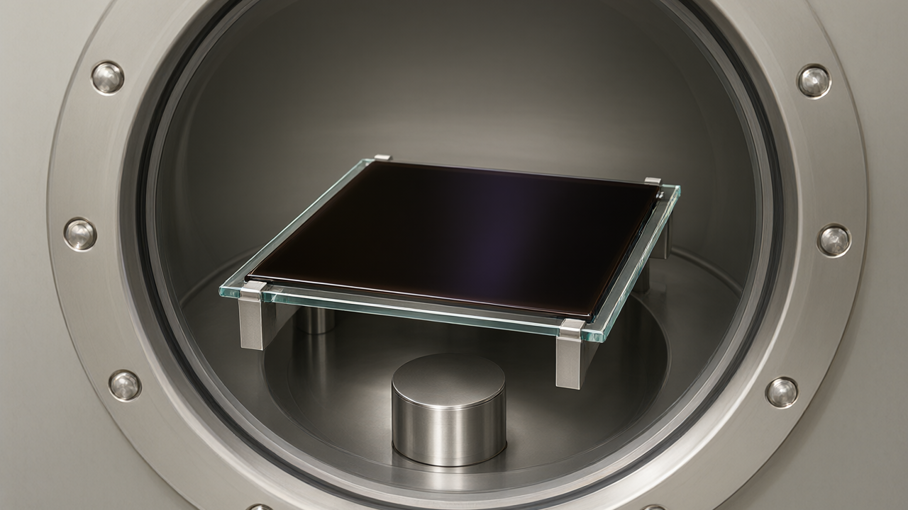
Unlike conventional co-evaporation, which requires separate sources for each component, Gas-FE uses a single pre-formulated, ball-milled perovskite powder. The process operates as follows:
- An auger screw feeds the powder into a nitrogen gas flow to create an aerosol.
- The aerosol passes through a vaporizer heated to 500 °C.
- Vapor is delivered via a heated showerhead onto a temperature-controlled substrate holder.
- The system operates at a roughing-pump vacuum of approximately 10 mbar.
The researchers demonstrated the ability to transfer components with widely different volatilities, including lead iodide, formamidinium bromide, methylammonium iodide, lithium TFSI, benzylphosphonic acid, amantadine hydrochloride, and guanidinium iodide. X-ray diffraction also confirmed film formation from mixed-cation and mixed-halide FA/Cs powders.
Background & Context
Traditional co-evaporation becomes increasingly complex as formulations include more trace additives, often requiring hours of deposition time. Previous flash-evaporation methods were limited by the throughput of feeding powder into a heated crucible. Gas-FE addresses these bottlenecks and shortens the turnaround time between batches compared to high-vacuum deposition.
Significance & Outlook
As a proof-of-concept, 250 nm films were integrated into a fully vacuum-deposited p-i-n solar cell (glass/FTO/MeO-2PACz/perovskite/C60/SnO₂/Cu). The best 0.05 cm² device reached a power conversion efficiency of 9.6%, with an open-circuit voltage of 0.91 V, a short-circuit current density of 16.8 mA/cm², and a fill factor of 63.3%. The team indicates that future improvements should target trap density and interfaces to address the current spread in voltage and fill factor.
Get our weekly technology intelligence — free
Receive an infographic that lets you judge at a glance whether each field’s analysis report is worth reading.
Subscribe Free — Weekly Tech Intelligence
By subscribing, you’ll receive Troy-Technical’s weekly technology intelligence newsletter.
- Your email and selected fields are used only to deliver the newsletter.
- We never share your information with third parties.
- You can unsubscribe anytime via the link in each email.
See our Privacy Policy for details.
Takes about a minute · Unsubscribe anytime